BrainVoyager v23.0
Projecting a Mesh in a VMR
It is often useful to check the relationship between a mesh and a VMR file, e.g. when verifying correspondence of coregistration or (automatic) cortex segmentation. An easy way to visualize this relationship is to project the mesh vertices into the underlying (hosting) VMR data set. This functionality is available in the Mesh Spatial Transformations dialog that can be invoked by clicking the Spatial Transformations item in the Meshes menu. A related function that fills the interior of the projected boundary is also available.
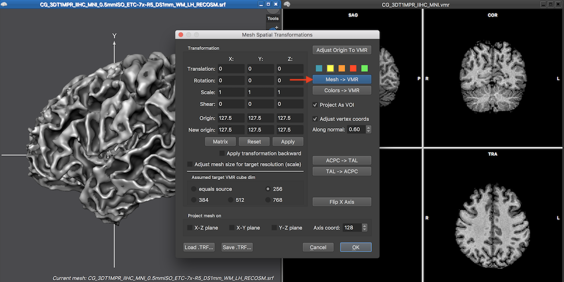
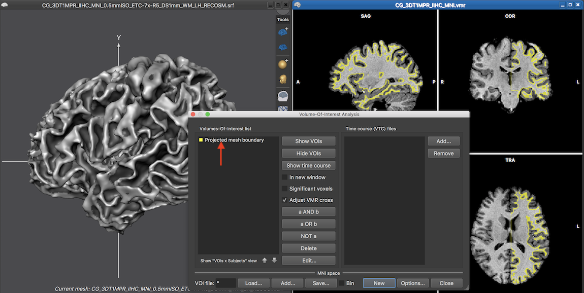
In the invoked dialog, a click on the Mesh -> VMR button will project the mesh contour in the VMR by color-coding the voxels closest to the position of the mesh vertices. The identified voxels are drawn as a VOI overlay in a color selected from the row of color icons (default yellow) above the Mesh -> VMR button (see figure above). Prior to BrainVoyager 20.2, the marked voxels were directly changed in the loaded VMR data set. In case one wants this behavior, the Project as VOI option need to be deselected before clicking the Mesh -> VMR button. In the screenshot above all default setting have been kept and the screenshot below shows a yellow overlay on the VMR associated with the left hemisphere mesh that was projected into the VMR. The resulting VOI is called "Projected mesh boundary" as default and appears in the Volume-Of-Interest Analysis dialog (see snapshot below) and can be hidden, shown and manipulated as any VOI.
When a mesh is reconstructed, the created vertices follow the outer boundary of voxels. If the voxel resolution of a VMR is, for example, 1 mm in all dimensions, the vertices of a mesh will be shifted half a voxel to model the reconstructed faces of a voxel (a voxel at position x = 7 is assumed in BrtainVoyager to extend from 6.5 to 7.5). The boundary of a mesh is thus "expanded" with respect to the center coordinates of voxels, which will be also reflected in the projection into the VMR since coordinates will be rounded to the next integer; a voxel at e.g. coordinate x=3.5 would mark voxel 4 not voxel 3 in the x dimension. While mesh coordinates will not fall exactly "between voxels" due to mesh smoothing operations, one might want to "undo" this expansion effect by traversing half the voxel size "backward", i.e. by lettng each vertex move inside the mesh along the vertex normal. This adjustment is turned on as default (since version 21.0) and can be checked or unchecked by clicking the Adjust vertex coords option. The Along normal spin box can be used to change the step size performed by each vertex along its normal in the "inside mesh" direction. In a cortex mesh, the direction inside the mesh would correspond to a step towards white matter.
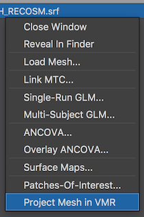
As a quick way to project a mesh in the associated VMR, the context menu can be used, which can be invoked by right-clicking the title bar of the current mesh document. The screenshot above shows the context menu highlighting the Project Mesh in VMR item. Using this option will perform the projection in the same way as if one would performed it from the Mesh Spatial Transformations dialog with default settings. The chosen color for the projection and thus resulting VOI color is thus also yellow. In case one wants to change default settings, one needs to use the Mesh Spatial Transformations dialog.
From Mesh Boundary to Center of Voxels
The step size appearing in the Along normal box is in units of millimeter and the recommended value is usually correct. When the mesh is projected into the VMR, the Along normal value is converted from millimeter (mesh) space into voxel space dividing the value by the current VMR's voxel resolution. If a VMR has a resolution of 1mm, a 0.5 mm correction step in mesh millimeter space will thus result in a shift of half a voxel "inwards" in VMR space correcting for the fact that the mesh has been reconstructed along a boundary on the (outside) faces of voxels. If the same mesh is, however, projected in a VMR with a 0.5 mm voxel resolution, a 0.5 mm step in mesh space will result in a (correct) shift of 1 voxel in VMR space. The calculated decimal voxel values are then rounded to get the integral voxel coordinates that are included in the resulting "Projected mesh boundary" VOI.
If a mesh is reconstructed from a VMR with a voxel resolution of 0.5 mm, the reconstructed mesh will create a surface shifted 0.25 mm (half voxel size) to the outside faces of voxels. When projecting the surface mesh back into the 0.5 mm VMR, a specification of 0.25 mm (default) will result in the correct voxel displacement resulting in half a voxel displacement (0.25/0.5 = 0.5). If, however, the mesh reconstructed from a 0.5 millimeter resolution VMR is projected in a VMR with 1.0 millimeter resolution, the same value of 0.25 will result in a voxel displacement of 0.25 along the normal (0.25/1.0 = 0.25), which is indeed the correct value in that case.
Following this reasoning, the value in the Along normal should be half the resolution of the VMR that was used when the mesh was originally reconstructed. The recommended value is actually a bit larger (0.6 times the VMR resolution) to get slightly better results after mesh smoothing. Since version 21.0 of BrainVoyager, newly reconstructed meshes actually store the resolution of the original VMR inside the mesh data, and also save this value to disk for later use. Note that projecting a mesh in a VMR with another resolution than the original one is a very useful possibility, for example when using a VMR with an upscaled resolution (e.g. 0.5mm) in the context of advanced segmentation that is then projected into the non-upscaled VMR (e.g. 1.0 mm resolution). Also when using sub-millimeter resolution VMRs, the VMR resolution of a recorded sub-millimeter anatomical scan might not be the same as the (rescaled) resolution of a VMR that matches the resolution of functional data. In such cases it is important to know the original resolution of the VMR from which the current mesh was reconstructed when using the mesh-into-VMR projection function.
In case that the original resolution value is not available, the suggested Along normal correction value is approximated as half the resolution of the currently used VMR. As detailed above, this is correct in case the resolution of the current VMR is the same as the one used to reconstruct the mesh, otherwise the value needs to be adjusted for best results.
If a mesh is projected in a VMR, also the center of the VMR data set might be different as the center of the VMR that was used when reconstructing the mesh. This can even happen if the VMR has the same voxel resolution. If, for example, a VMR is transformed into ACPC/TAL space to perform cortex segmentation and the mesh is afterwards back transformed in native space, the center coordinates might have changed in case that the original VMR had not the same bounding box values (e.g. 256 or 384) in all dimensions. In order to shift the mesh vertices to fit to the center of the currently loaded (mesh hosting) VMR, the Adjust Origin To VMR button can be used. While necessary spatial shifts could also be calculated and manually entered by changing the values in the New origin coordinate fields followed by a click on the Apply button, this function is providing a quick fix in case one observes a shift in one (or more) axes when projecting a mesh into a VMR with different dimensions than the dimensions of the VMR used when the mesh was reconstructed.
Copyright © 2023 Rainer Goebel. All rights reserved.