BrainVoyager v23.0
IA Using Corresponding Points
When no header information is available or in cases when a 3D data set has been recorded in a different session as the functional data, the mathematical header-based initial alignment of functional (or diffusion-weighted) and anatomical data is not applicable. In this case, it is possible to align the two data sets quickly by specifying three (or more) corresponding points in the two data sets. When running the initial alignment steps, the specified points in the 3D data set act as landmarks to which the corresponding points marked in the FMR will be aligned as close as possible.
Note. The descriptions below need only be consulted in case of problems with the automatic header-based initial alignment.
Preparation of the functional volume
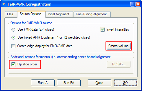
As with all coregistration methods, the target VMR file has to be loaded first. Then a source FMR file is selected in the Files tab of the FMR-VMR Coregistration dialog (for details, see section Coregistration of Functional and Anatomical Data Sets). To use the corresponding points alignment, the referenced AMR file (or the first volume of the specified FMR file) must be transformed into a 3D data volume with the same resolution as the VMR file. For this transformation, the program uses the voxel resolution values stored in the selected FMR file. To build the functional source volume, click the Create Volume button in the Source Options tab of the FMR-VMR Coregistration dialog. This step is not necessary, if the FMR file has been selected prior to entering the FMR-VMR Coregistration dialog by using the Select FMR button in the Coregistration tab of the 3D Volume Tools dialog. Using the Create Volume button has, however, the advantage, that further settings can be specified, i.e. whether a linked AMR file or the first set of functional slices should be used to build the functional volume. Even more importantly, you can turn on or off the Flip slice order option prior to clicking the Create Volume button. This option is important to match the source and target volume with respect to the same - neurological or radiological - convention. If, as in our example, the target VMR file is in radiological convention (left-is-right) and if the functional slices progress from the inferior part of the brain to the upper part of the brain if one moves from the first (number 1 in FMR project) to the last one, the functional slices have to be flipped. Therefore the respective option has been turned on in the snapshot below for our example data. Without header information, the best way to find out whether the functional slices should be flipped is to perform the sagittal orientation procedure as described next and then to check whether prominent points in the brain look similar in both volumes or whether they appear on the wrong side. In the latter case, a slice order flip is necessary and the volume should be re-created using the Create Volume button with the modified Flip slice order option.
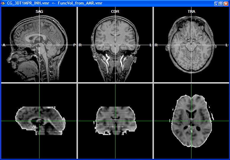
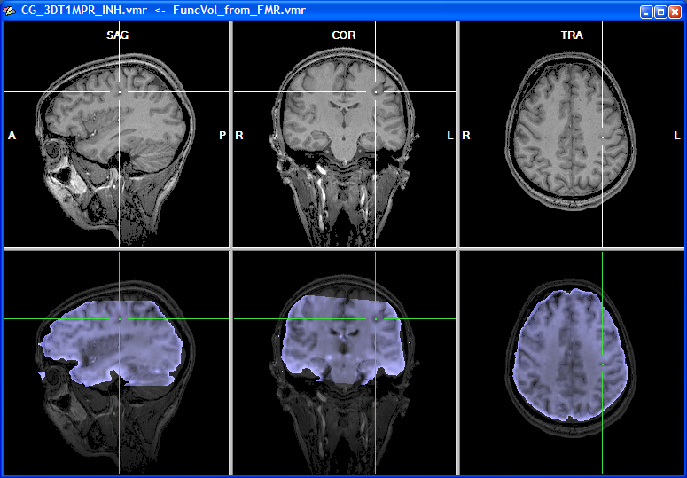
When the functional volume has been created after a short moment, the target VMR data set is shown in the upper row and the source volume, representing the functional data, is shown in the lower row of the VMR window. Since functional data is usually recorded in axial or coronal slices but rarely in sagittal orientation, the two data sets do not possess the same orientation as shown in the snapshot below.
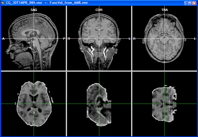
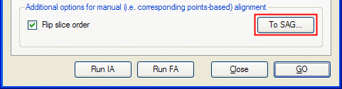
The left subwindow in the lower row shows the original orientation of the functional data set, which is axial in this example. The other two subwindows in the lower row depict two other orthogonal views revealing that the original functional slices have been indeed transformed into an iso-voxel 3D volume. The voxel size of the functional 3D volume now corresponds to the one of the intra-session VMR data set (i.e., 1mm x 1mm x 1mm voxels). For the corresponding points alignment, a minimum of three points have to be specified in both data sets reflecting the same anatomical landmarks. The localization of these corresponding points is, however, difficult if the two data sets have a different basic orientation. In order to simplify the specification of corresponding points, the functional data can be first rotated into the same sagittal orientation as the VMR data set. To orient the functional volume into the standard sagittal orientation, click the To SAG button in the Additional options for manual alignment field. This button is disabled (see snapshot of the FMR-VMR Coregistration dialog above) until the functional volume is available.
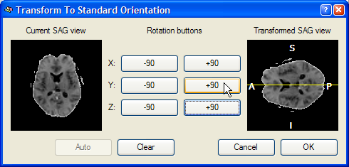
After clicking the To SAG button, the Transform To Standard Orientation dialog appears as shown in the snapshot below.
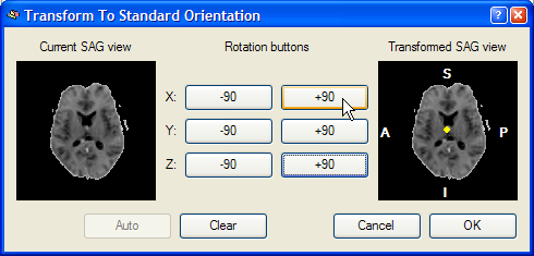
This dialog shows a Current SAG view image of the left side, which is a copy of the sub view on the left side of the lower row of the VMR window. The goal of this reorienting tool is to provide a visual tool to reorient the functional volume in such a way that the Transformed SAG view image of the right shows a standard sagittal view. Depending on the start orientation, the proper reorientation can be achieved in one or more steps by clicking repeatedly on the various -90 and +90 buttons, which perform 90 degree rotations around the three basic axes. When moving into one of the buttons, helping yellow lines or a yellow point indicate the axis around which the 90 degree rotation will be perfomed. In the snapshot below, the mouse cursor has been moved into the +90 button for the X axis and a yellow point is shown in the middle of the Transformed SAG view image. This point indicates that the image will be rotated around the axis running through the image plane. After clicking the +90 button, the following intermediate state is shown:
The mouse cursor is now moved into the +90 button for a Y axis rotation, which is indicated by a yellow line running from left to right through the middle of the image on the right. After pressing this button, the following result is produced:
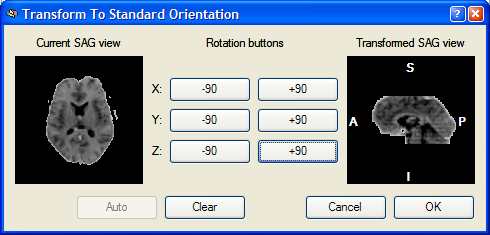
The Transformed SAG view image now shows the standard sagittal orientation as used in BrainVoyager. After clicking the OK button, the visually defined spatial transformation is applied to the functional volume in the VMR window as shown in the snapshot below.
Having now both a sagittal orientation for the source functional volume and the target anatomical volume, the subsequent specification of corresponding points is significantly simplified.
Specification of corresponding points
To specify corresponding points, close the FMR-VMR Coregistration dialog and click on the Define Points button in the Corresponding points coregistration field of the Coregistration tab of the 3D Volume Tools dialog. This will open the Corresponding Points dialog, which records the coordinates of the specified source and target point pairs.
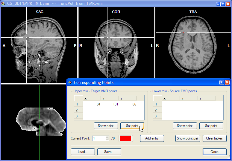
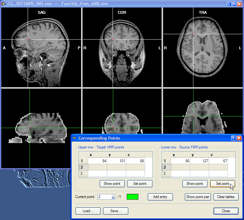
Corresponding points can now be conveniently specified by changing the position of the cross in the upper and the lower row, respectively. Note that the two crosses are decoupled, i.e. they can be moved in the respective volume independently from the cross position in the other volume. At least three corresponding points have to be specified before the corresponding points alignment routine can be performed. To specify a point, select it in the upper row and then click the Set Point button in the Upper row - Target VMR points field. In the snapshot above, a region at the anterior insular has been specified since this region can be not only identified easily in an anatomical scan but also in a functional scan. As long as the three points are not falling on a line, you may choose any points you want for corresponding points alignment. The snapshot shows the Corresponding Points dialog just after the Set Point button has been clicked. When the point is defined, the position at the cross is highlighted with a red point and the coordinates of the point is shown in the first row of the table in the Upper row - Target VMR points field. After having specified the point for the upper row, select the corresponding point in the lower row by positioning the cross accordingly as shown in the snapshot below for the point selected in this example:
After clicking the Set Point button in the Lower row - Source FMR points field, the coordinates at the cross position are copied into the first row of the table on the right and highlighted with a red point. This completes the definition of the first corresponding point. The program now automatically highlights the second row to let you enter the second corresponding point pair. You may, however, go back to the first corresponding point pair at any time by changing the entry in the Current point spin box. You can, for example, correct the position of the cross and then re-click the Set Point button for the upper and/or lower row. You may also use the Show Point buttons to move the cross to the position specified for the point pair selected in the Current point spin box. As a convenience function, the Show Point Pair button is moving the cross both in the upper row and the lower row to the respective positions of the currently selected point. Note also that each corresponding point pair is defined in a different color. You may change the color for a point pair by clicking on the Current Point Color button.
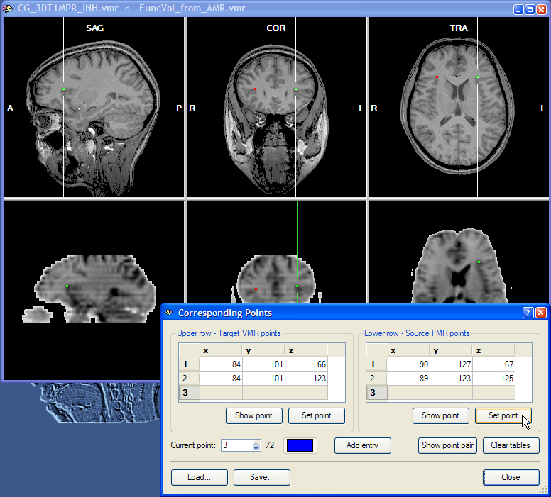
The second point pair can now be specified in the same way as the first corresponding point, i.e. by moving the cross in the upper and lower row to corresponding positions. In the snapshot above, the second point pair has been located in the posterior part of the insular in the left hemisphere. Finally, the third point can be specified.
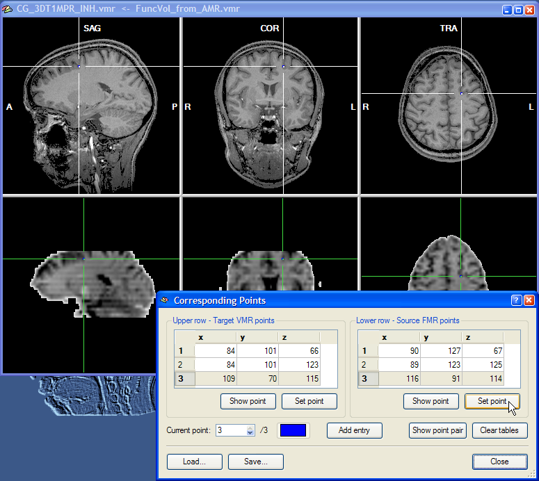
This completes the specification of a minimum of three corresponding points. Specifying more than three points can improve the alignment since specification errors tend to cancel each other out. If you want to specify more points, click the Add Entry button once for each additional point pair. You may also save the specified corresponding points by clicking the Save button. This might be useful in case you want to modify the point definition at a later time.
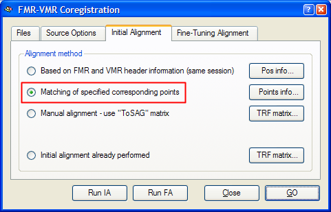
After having specified the corresponding points, click the Close button to leave the Corresponding Points dialog. Click the Align button in the Corresponding points coregistration field in the Coregistration tab of the 3D Volume Tools dialog. This will re-open the FMR-VMR Coregistration dialog. Switch to the Initial Alignment tab. The program will have automatically selected the Matching of specified corresponding points option as the method for initial FMR-VMR alignment in case that at least three corresponding point pairs have been defined. You may now perform the initial alignment by either clicking the Run IA button or the GO button. In the latter case, the fine-tuning step is started after application of the corresponding points initial alignment. To see the initial alignment result in isolation, it is recommended to click the Run IA button and then proceed with the fine-tuning alignment as a separate step.
The snapshot above shows the result of the initial alignment step for our example data. The obtained result is at least as good as the one obtained using the header-based alignment for the same data (see section IA Using Header-Based Coregistration, which also describes different ways how to judge visually the achieved alignment).
Tips and remarks. Note that for judging whether a corresponding point is specified correctly in both volumes, you can only base your judgement on the appearance of the local neighborhood of the two points in the respective three orthographic sub views since the two data sets are rotated with respect to each other. To aid in finding corresponding points, enlarge the two-rows view as much as possible, i.e. by closing the Sidebar on the left side. From visual saliency, it appears that corner points of ventricles are good landmarks to use. Note, however, that these points suffer from distortions in the functional EPI images and therefore other points should be used. If you have recorded T1-weighted coplanar images and linked as an AMR file, you can, of course use ventricle points as landmarks because T1-weighted images do not exhibit spatial distortions at tissue inhomogeneities.
When specified points are saved to disk in a "CPS" file, the program saves not only the coordinates of the corresponding points but also a flag specifying whether he functional data has to be flipped or not and a spatial transformation matrix for the sagitall orientation of the functional data (if applied). The CPS file "ObjectsCorrespondingPoints.cps" saved for the example data looks like this:
FileVersion:             2
NrOfCorrespondingPoints: 3
 84.00
101.00  66.00
    90.00
127.00  67.00
84.00 101.00 123.00     89.00
123.00 125.00
109.00  70.00
115.00    116.00
 91.00 114.00
CreateFMR3DMethod:       3
SourceToSAGMatrix:
0.0000 0.0000 1.0000 0.0000
1.0000 0.0000 0.0000 0.0000
0.0000 1.0000 0.0000 0.0000
0.0000 0.0000 0.0000 1.0000
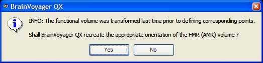
When you reload a CPS file at a later point, the program detects whether a sagittal reorientation has been performed prior to specifying the corresponding points. You should click the Yes button in this case, otherwise the loaded point coordinates will not be appropriate.
Copyright © 2023 Rainer Goebel. All rights reserved.