BrainVoyager v23.0
Coordinate Systems
This topic aims to provide knowledge about coordinate systems, how they are providing frames of reference and how frame matrices can be used to express the same location in different reference frames. Furthermore, the order and direction of the axes used in DICOM and NIfTI files are explained and how they are converted to the internal BrainVoyager axes system. The information provided in this topic is also useful to understand how NIfTI files are processed by BrainVoyager. To get the most out of the presented information it is useful to read the topic about spatial transformation matrices first since reference frames use the same 4x4 matrices containing orientation (rotation) and origin (translation) information.
Coordinates and Matrices as Change of Frame
In the previous topic, spatial transformation matrices were introduced to express and combine elementary spatial transformations (translations, scales, rotations, shears) in a single 4x4 homogenoeus matrix that can be used to map points (or vectors) from one space to another space (indicated in the panel on the left side in the figure below). A matrix fulfilling special restrictions can also be interpreted as a cartesian three-dimensional coordinate system. These matrices can be used to express coordinate system changes: Given the location in one coordinate system, a matrix can be used to express the same location in another coordinate system or frame of reference (see panel on the right side in the figure below).
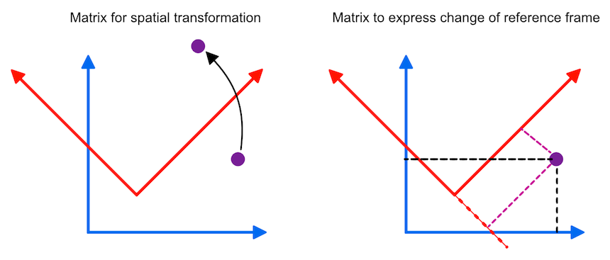
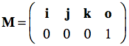
Such a coordinate system contains a point which is called the origin, from which three mutually perpendicular axes are constructed that are referred to as the X-axis, the Y-axis, and the Z-axis (the figure above only shows two axes). The origin is, thus, at the intersection of all three mutually perpendicular axes. One branch of each axis with respect to the origin represents positive values while the other branch on the opposite side of the origin represents negative values (not shown in the figure above). With these three axes any point p in space can be assigned three coordinates p=(px, py, pz) that are the signed distances along the three axes from the origin. More specifically, points and vectors can be expressed in terms of the unit vectors, i, j and k forming an othonormal basis set. The term "orthonormal" means that these vectors are mutually perpendicular with a normalized length of 1, i.e. these vectors are unit vectors in the positive X, Y, and Z direction, respectively. In terms of coordinates, the unit vectors in the standard (world) coordinate system can be written as i=(1,0,0), j=(0,1,0) and k=(0,0,1). Any three-dimensional point or vector can then be expressed as a weighted sum (linear combination) of scalar multiples of these unit vectors in the form p=(px, py, pz) = pxi + pyj + pzk. Coordinates are thus defined as the weights of the basis vectors. The three basis vectors together with the position of the origin o are also called a (reference) frame. Like transformation matrices, a frame can be expressed in homogeneous coordinates as a 4x4 matrix where the unit vectors and origin are stored as 3-element column vectors:
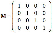
Multiplying the frame matrix with a point p , p' = Mp, results in the linear combination with the coordinates of p plus the position of the origin. With the standard unit vectors and the origin at (0,0,0), the standard reference frame simply is:
Since this is the identity matrix, any point will be expressed with unchanged coordinates when performing the matrix-vector multiplication. If we have, however, another frame MR in which points are expressed, we can use the frame matrix itself to re-express local coordinates in the standard (world) coordinate system. This can be demonstrated with the right pane of the figure above where the blue coordinate system represents the standard frame M and the red coordinate system represents a rotated and shifted frame MR. Note that the depicted point is not moved, but has other coordinates in the red coordinate system than in the standard (blue) coordinate system. Lets assume the following frame matrix for the red coordinate system:
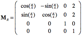
This matrix specifies the position (frame origin: X=2, Y=2) and orientation (upper left 3x3 rotation sub-matrix: 45 degrees (π/4) rotation around the Z axis) of the red coordinate system. With this matrix, the coordinates of any point pR in the red coordinate system can be re-expressed in the standard (blue) coordinate system simply by the matrix-vector product p = MRpR. And inversely, the coordinates of any point p in the standard coordinate system can be expressed as coordinates in the red coordinate system simply by using the inverted frame matrix: pR = MR-1p. Calculating the inverse of a frame matrix is easy involving only the transposition of the upper left 3x3 sub-matrix (inverse equals transpose for orthonormal matrices) and the negative of the origin vector.
In the context of volume MRI data, this implies that one can simply multply any voxel coordinate by the volume's frame matrix to express the voxel coordinates in scanner (world, standard) coordinates. And a position in scanner (world) coordinates can be expressed in the frame of the MR volume by simply multiplying the scaner space coordinates with the inverted frame matrix. But where do the frame matrices for MRI volume data come from? They can be constructed from the header information stored in major neuroimaging file formats as will be shown below for DICOM and NIfTI images. The possibility to express any point in one coordinate system in another coordinate system using frame matrices can further be used to align two data sets measured in the same scanning session using their respective frame matrices M1 and M2. Instead of re-expressing coordinates of both volumes in scanner space, one can combine the two matrices to go directly from one of the volumes to the other volume by first going to scanner space from the first volume and then going into the space of the second volume. These two steps can be combined by multiplying the frame matrices of the two volumes: M=M2-1M1. The combined matrix M now re-expresses voxel coordinates in one (e.g. functional) space in the space of the other (e.g. anatomical) volume. This approach is used in BrainVoyager's header-based FMR-VMR alignment as described below.
BrainVoyager Coordinate Systems
For historical reasons BrainVoyager uses a space that is based on sagittal structural images measured on Siemens scanners of the 1990s. BrainVoyager's internal data orientation is therefore also called "sagittal" coordinate system. The first (X) axis stored in BrainVoyager volume (VMR) files contains thus values increasing anterior to posterior, the second axis (Y) contains values increasing superior to inferior, and the third axis (Z) contains values increasing right to left (radiological file convention) or left to right (neurological file convention). This results in a PIL+ (or PIR+) file coordinate system when expressing the order of axes as a three letter code. Note that the "+" symbol indicates that letters are abbreviations for the "to" direction, i.e. they denote the direction for increasing voxel index values. While the data is usually stored in BV's internal PIL+ coordinate system, coordinates are presented to the user in a LAS+ or RAS+ system with common axes names, i.e. X for right-left or left-right, Y for anterior-posterior and Z for inferior-superior coordinates. Note, however, that the user-presented axis values are still using voxel coordinates (indices into 3D array) and not a standard millimeter space with a common origin (the center of the volume is used as the origin). The presented LAS+/RAS+ voxel coordinates are referred to as "system coordinates" in BrainVoyager, for example in the 3D Volume Tools dialog. When a data set is explicitly normalized to MNI or Talairach space, the same LAS+/RAS+ coordinate system is used but displayed coordinates are relative to the respective origin (AC for Talairach, close to AC for MNI-152) as reported in publications. The respective LAS+/RAS+ coordinates are referred to as "MNI" or "Talairach" coordinates and are displayed in addition to the system coordinates. BrainVoyager's 3D Viewer displays TAL/MNI coordinates but also uses and shows the native OpenGL coordinate system.
DICOM Coordinate System
The DICOM standard "Reference Coordinates System" (RCS) defines the location of the image with respect to the body of the scanned person (usually referred to as patient). It is assumed that one looks from the bottom of the scanner upwards, or more simply that one looks in the face of the patient (this view is often referred to as the radiological convention). For this scenario (and the usual supine scan position in MRI studies), the patient coordinate system is the same as the Scanner world coordinate space. The X axis thus goes from right to left, the Y axis goes from anterior to posterior (front to back), and the Z axis goes from inferior to superior (feet to head). This can be summarized as a LPS+ coordinate system.
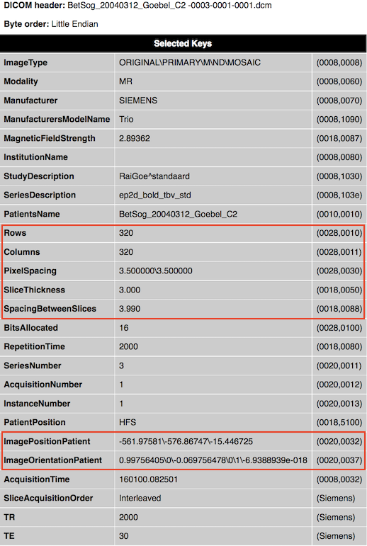
The DICOM standard specifies that 2D images are stored row by row, i.e. the first row is stored from left-to-right (left upper corner), followed by the second row from top to bottom. The position of an image in 3D space is indicated in a coordinate system using orientation and position 3D vectors. The (normalized) orientation vectors indicate how much an image is rotated with respect to its coordinate system, and the position vector indicates the location of the image with respect to the origin. The orientation vectors can be found in the tag ImageOrientationPatient (0020, 0037). The first three values (direction cosines) represent the vector for the image orientation of the X-axis, and the fourth, fifth and sixth values indicate the vector for the image orientation of the Y-axis. These raw values are shown in the displayed (partial) header when BrainVoyager reads raw DICOM data (see snapshot below for an example file with values [0.99756405, 0, -0.069756478] for the X axis and values [0, 1, -6.9388939e-018] for the Y axis). The values for the Z axis are not explicitly stored in the DICOM header but since the third axis must be orthogonal to the first two axes, it can be simply computed as the cross product of the x and y vector (resulting in the values [0.0698, 0, 0.9976]). Since the values for the three axes are close to the wordl coordinate axes (X: 1,0, 0, Y: 0, 1,0, Z: 0, 0, 1), it is evident that this particular data set has not been rotated much with respect to the world coordinate system. Note that the second example file from an anatomical scan, shows instead a 90 degree reorientation with respect to the world coordinate system.
Note that the extracted DICOM header information is not automatically stored to disk. In order to obtain header .html files from selected DICOM files, one can use theExtract DICOM Headers item in the File menu. It is also possible to anonymize DICOM files (only patient name at present) using theAnonymize and Rename DICOM Files item in the File menu.
While the ImageOrientationPatient field specifies the orientation of a DICOM file, the imagePositionPatient field provides the location of the image (see snapshot above, the three values for the example file are [-581.97581, -576.86747, -15.446725]. Note that the position vector of DICOM files points to the upper left hand corner of the image, or more precisely, to the center of the first transmitted pixel of the data. In order to know the extent of the whole image in Scanner space, information about the size of image pixels is required, which is provided as the distance between the center of neighboting pixels in mm for both image dimensions in the PixelSpacing field (adjacent row and adjacent column spacing). In order to correctly stack images of a multi-slice scan, information about the slice thickness is also needed, which is provided in mm in the SliceThickness and SpacingBetweenSlices field. The latter value is more important since it also contains potential gap between slices, i.e. it represents an "effective" slice thickness. To fully represent the image in space, its dimensions are needed, which are provided in the Rows and Columns> fields. Note that the image dimension values 320x320 in the example are very large for a functional (GE-EPI) image; the reason for this is that this image is a special SIEMENS "Mosaic" image that contains all slices from a functional volume in a single DICOM file.
For convenience, BrainVoyager does not store the position of the first pixel but the position of the center of the slice, which is calculated as:
The original DICOM orientation and position vectors are stored in the headers of volumetric BrainVoyager document files (VMR, FMR, DMR). The figure below shows the stored information for a functional (FMR) document on the left and for an anatomical document (VMR) on the right. The respective Scan Positioning Information dialogs can be invoked by
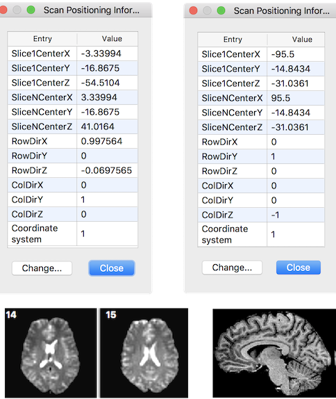
The row and column direction vectors are named "RowDir" and "ColDir" respectively. From the provided DICOM information a transformation matrix can be created that maps pixel coordinates of input vector x (pairs of indices into image array) to mm scanner world coordinates (y):
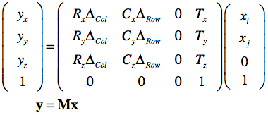
The row and column direction vectors from the ImageOrientationPatient field are named R and C respectively; the adjacent column and row distance values from the PixelSpacing field are named as ΔCol and ΔRow respectively. Note that for the first voxel (i = 0, j = 0), the direction-related terrms are 0.0 and the equation results in the translation vector T containing the values of the ImagePositionPatient field as the origin of the image. Note that the T vector will be different for each DICOM image that belongs to a stack of slices froming a functional or anatomical 3D volume. With index k going through the slices, the equation to map any voxel of a volume from indices to scanner space becomes:
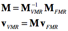
The transformation matrix is important since it allows to bring two scans from the same scanning space into coregistration as is performed when running the FMR-VMR coregistration in BrainVoyager. Instead of mapping both volumes in the same scanner space, a more elegant approach is to keep one volume as is and perform two transforms on the other volume. In a first step, the FMR volume is brought into scanner space by applying its DICOM transformation matrix. In the second step the transformation matrix of the VMR volume is applied backwards from scanner space to the space of the VMR volume. Before application to the coordinates of each voxel of the FMR volume, the two matrices can be multiplied to create a single transformation matrix for FMR-VMR coregistration:
The matrix inversion can be perfomred easily involving mainly a transposition of the 3x3 rotation matrix (after removing the scale component). The outlined procedure is used during the "header-based FMR-VMR initial alignment" in BrainVoyager. Because voxels need to be interpolated, the procedure is executed backwards in practice, i.e. the voxel space of the target VMR is traversed, the inverted M matrix is applied and the reached coordinates (float values) in the source FRM volume are sampled from the surrounding voxels using one of the available interpolation methods (nearest neighbor, trilinear, cubic spline, sinc).
Notes. In case that the VMR data is not scanned in sagittal orientation, an additional ortho-reorientation matrix is applied. The FMR and VMR matrices store the center of the respective 3D data sets instead of the position of the first voxel of the first slice. The initial alignment FMR-VMR transformation matrix M does not store scale values (only orientation and center position since it represents an ortho-normal frame matrix), which are added from the involved FMR and VMR data sets when actually performing the initial alignment.
NIfTI Coordinate Systems
While NIfTI files support multi-dimensional data sets, the following description focuses on how the 3 spatial dimensions are oriented in space. The NIfTI coordinate system stores an affine spatial transformation matrix that maps ijk voxel coordinates in a RAS+ coordinate system, i.e. after applicatin of the matrix the resulting first (X) axis runs from left to right, the resulting second (Y) axis runs from posterior to anterior and the resulting third (Z) axis runs from inferior to superior. This is the same coordinate system used in MNI and Talairach space (but with a different origin if data is in non-normalized space). The inclusion of the spatial transformation matrix M in the header allows to store data in the NIfTI file itself with an arbitrary order of axes and directions since the matrix ensures that if the file-based voxel coordinates (i.e. the i,j,k indices into the first, second, third array dimension) are multiplied by the transformation matrix M, the resulting volume data will be located in a RAS+ coordinate system:
Inversely, since the output coordinate system (RAS+) is known, one can invert the transformation matrix to obtain the axes order and direction as stored in a NIfTI file. Note that when opening NIfTI files, BrainVoyager shows the included transformation matrix as well as other information of the NIfTI header in a HTML dialog window (see snapshot below showing the header of a 4D file).
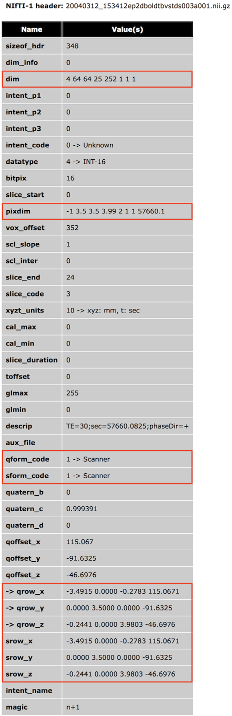
The NIfTI format has two methods to specify the transformation matrix that maps voxel i,j,k coordinates to RAS+ world coordinates. One method (method #2, qform) is based on a rotation matrix (stored as a quaternion), scaling values and a translation vector; this method is mainly used to map voxel coordinates to x,y,z coordinates in scanner world space (or to another aligned data set). The other method (method #3, sform) uses a full 12-parameter affine matrix to map voxel coordinates to x,y,z MNI-152 or Talairach space, which also use a RAS+ coordinate system. While both matrices (if present) are usually the same, one could store both a scanner (qform) and normalized (sform) space RAS+ matrix so that the NIfTI file and one could interpret the data in non-normalized and normalized space depending on the situation at hand. Often a normalized data set is however, stored in MNI-152 or Talairach space, and the transformation matrix is then simply the identity matrix (eventually with some scaling and axes reorientation). A third method is available that only supports scaling the data (using the NIfTI pixdim values) without defining a coordinate system; this method is not recommended and only included in the NIfTI specification for compatibility with the older Analyze 7.5 file format. In the following it is assumed that a transformation matrix for raw image data is provided to map voxel coordinates into scanner world space; for such non-transformed original data it is described how the NIfTI coordinate system is used in BrainVoyager for FMR-VMR coregistration. The topic Processing NIfTI Files contains more details on how BrainVoyager processes NIfTI files. As default, BrainVoyager does not resample anatomical (VMR) and functional (FMR) data sets when reading NIfTI files that contain a transformation matrix mapping voxel coordinates into scanner world space (qform_code or sform_code = 1) since it assumes that the data represent original (measured) slice data (usually converted from DICOM files or proprietary scanner manufacturer files). For inspection and to be available for subsequent FMR-VMR coregistration, the transformation matrix from the NIfTI header is stored in the respective VMR and FMR BrainVoyager files.
To be visualized in BrainVoyager's standard "sagittal" view, VMR files are reoriented using only multiple of 90 degree rotations (and eventually axis flips); the respective VMRijk-BV transformation matrix is created by multiplying a VMRijk-orthoRAS and a VMRorthoRAS-BV matrix. These ortho-transformations do, however, not require resampling of the data. FMR data sets on the other hand are shown as a set of slices along the Z axis of the NIfTI file without any spatial transformation applied.
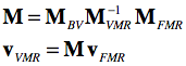
For FMR-VMR coregistration the same logic is applied as described above for DICOM files. Instead of mapping both volumes to the same scanner space, one volume (usually the VMR) is not changed serving as the target space while the FMR data undergoes a series of transformations. In the first step, the FMR volume is brought into scanner space by applying its NIfTI FMRijk-RAS transformation matrix. In the second step the NIfTI transformation matrix of the same-session VMR data is applied backwards from scanner world space to the ijk array in the oriignal NIfTI file: VMR-1ijk-RAS = VMRRAS-ijk. In case that the VMR file would directly represent the data as stored in the original NIfTI file (like the FMR does), we would be done at this point. Since a VMR file stores the data reoriented to BV standard space when reading a 3D NIfTI file, the described VMRijk-BV transformation is appended to finally reach the VMR space as represented in BrainVoyager's internal PIL+ coordinate system. The three matrices, FMRijk-RAS (MFMR), VMRRAS-ijk (M-1VMR) and VMRijk-BV (MBV) can be multiplied to create a single transformation matrix M for FMR-VMR coregistration mapping voxel coordinates in FMR space to voxel coordinates in VMR space:
The matrix M is used as the header-based initial alignment (IA) matrix when running FMR-VMR coregistration. As for the DICOM case above, in practice the matrix is applied backwards, i.e. the voxel space of the target VMR is traversed and the inverted M matrix is applied to locate corresponding coordinates (float values) in the source FRM volume allowing to sample values of surrounding voxels using interpolation.
Notes. BrainVoyager stores the position of the center voxel in the NIfTI-to-RAS FMR and VMR matrices (MFMR and MVMR) instead of the position of the first voxel (i=0, j=0, k=0) in the translation (4th column) vector. Furthermore, the FMR-VMR alignment matrix M (as saved to disk in a .trf file) does not store scale values (i.e. only orientation and position (only orientation and position since it represents an ortho-normal frame matrix); the scale values are added from the involved FMR and VMR files when actually performing the initial alignment step.
Copyright © 2023 Rainer Goebel. All rights reserved.