BrainVoyager v23.0
DMR Project Creations
In order to analyze DWI data, the raw diffusion images for all directions must be integrated into a DMR ("diffusion MR") project. The raw data must contain at least one volume of non diffusion-weighted (b0) slices and at least six volumes with diffusion measurements in different directions. Recent DTI MR pulse sequences typically scan more than six diffusion directions and the same directions may be measured several times during a DWI scan. In the first step of anlysis, all raw measurements will be inegrated into a DMR project using the Create Project wizard (see snapshot below).
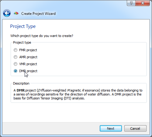
The wizard can be launched by clicking the Create Project Wizard icon in the Standard Toolbar or by clicking the Create Project Wizard item in the File menu. Click Next > to reach the Project Type page and select the DMR project type (see snapshot above). In the subsequent Raw Data Format page, select the type of your data: DICOM, ANALYZE or PHILIPS_REC. Click Next > to reach the Select Data Location page. Enter a name for your project in the Project name text field. Then click the Browse button and navigate to your data. In case of DICOM data, select the folder containing your raw data; for other formats, select the file containing the DTI measurements within the folder.
In the case of DICOM data, the program suggests renaming the files (if not already performed) in order to replace the original file names with more readable names. Renaming is performed using information found in the DICOM headers and is highly recommended since it ensures proper sorting of files. After renaming, file names will appear in the following naming scheme: "[scan info]-[series]-[volume]-[image].dcm".
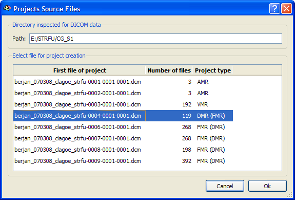
After having analyzed the file names in the specified folder, the program shows the Projects Source Files dialog (see snapshot above) containing a table with an overview of all scans detected in the folder. Each row of the table contains the name of the first file of a project (first column), the number of files belonging to the project (second column) and the presumed project type (third column). Select the row with the source file belonging to your DTI data (categorized as type "DMR" or "FMR") and click OK.
Click Next > to move to the Number of Slices page. If the displayed Number of slices value is not correct, replace it with the right value. Click Next > to move to the Number of Direction Volumes page. Check that the displayed Number of volumes value is correct, otherwise replace it with the correct value. You may also provide a gradient direction file now by using the Browse button on the right side of the Gradient direction file field. If you do not already have a gradient direction file for the selected DTI data set, leave this entry blank. Continue to the Summary page by clicking the Next > button. If you want to change anything, you may go back to previous screens, otherwise click the Finish button. Based on the selected options, the program will now create the DMR project.
After the DMR project has been created, the DMR Properties dialog pops up showing all essential information about the data, including number of volumes and number of slices. Similarly as with FMR projects, a DMR file is a descriptive text file and does not itself contain the diffusion data that is actually stored in a single DWI (diffusion weighted images) file. The DMR file, however, refers and describes the actual data in the associated DWI file. This description can be inspected and modified in the DWI Data dialog, which can be called by clicking the DWI Data button.
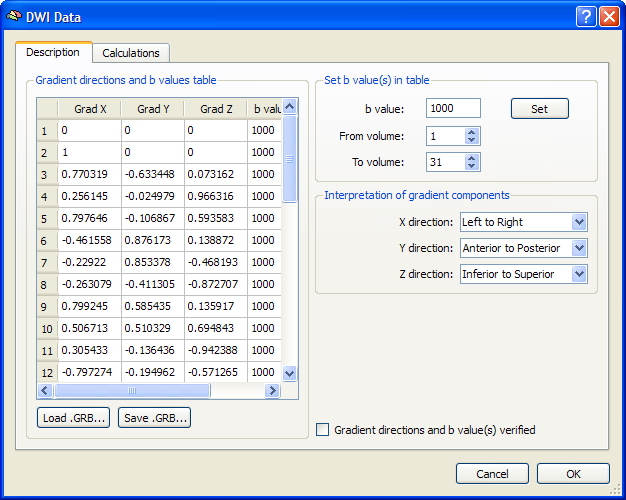
The most important information in the DWI Data dialog is the Gradient directions and b values table (see snapshot above) describing for each scanned volume the measured direction of diffusion as well as the used b value. In most DTI scans, the b value is the same for all directions. Each direction is specified by its associated x, y and z component. You may enter the values in the table or load a prepared text ("GRB" = gradients and b values) file using the Load GRB button. In case you need to manually enter the values, you may want to save the information to disk using the Save GRB button. This avoids entering the same information again for other DWI scans requiring the same direction table.
It is important that the diffusion direction table is interpreted in the right way, i.e. it must be specified how the first (x), second (y) and third (z)coordinate value in the table should be interpreted. The interpretation can be specified in the Interpretation of gradient components field by selecting the direction for the X axis (coordinates: x=1, y=0, z=0), Y axis (coordinates: x=0, y=1, z=0) and Z axis (coordinates: x=0, y=0, z=1). In the default assignment, the X axis points from left-to-right, the Y axis points from posterior-to-anterior and the Z axis points inferior-to-superior. If this assignment does not match the definition used for your scanner, you may change the axes interpretations using the three specification drop boxes.
If the gradient table is filled properly, diffusion tensors can be estimated.
Copyright © 2023 Rainer Goebel. All rights reserved.