BrainVoyager v23.0
Manual Segmentation Tools
While standard and advanced cortex segmentation tools usually produce good results, some manual corrections may be necessary if one wants to produce (topologically) correct brain segmentations. Manual segmentation tools are also needed in the context of non-standard tasks, e.g. when segmenting specific sub-cortical structures or when one needs to segment sections of cortex in cases of partial brain scans (slabs). The latter scenario may occur especially with sub-millimeter ultra-high field (7T and higher) data sets. Even if whole-brain anatomical data is available, it might be desirable to segment small cortical regions directly in the functional data in order to avoid small misalignments when sampling functional data at different cortical depth levels. Since the quality of functional (T2 or T2*) weighted images do not have optimal grey/white matter contrast, such tasks may need manual segmentations.
Tools in the Zoom View Pane
The Zoom View pane adds (access to) several useful tools supporting manual segmentation, including pixel-precise drawing, region filling, color selection, toggling between (blended) volumes, undo/redo history, creation of 3D meshes for all segments (colored labels) and so on. While the descriptions below describe certain functions referring to a mouse as input device, the same functionality is also available for built-in or external track pads. In order to see a short explanation (tooltip) about the function of a specific icon in the toolbar, hover the mouse cursor over an icon and wait a couple of seconds.
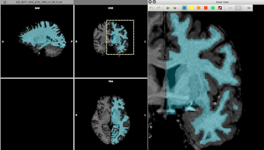
In order to use the Zoom View pane, a region in a VMR document (primary volume) need to be selected by holding down the ALT key while dragging with the mouse from the left-upper to the right-lower corner of the desired region. The selected region will be indicated by a stippled yellow rectangle in the VMR document and its content will appear in the Zoom View pane (see snapshot above).
Note for Linux. The CTRL+SHIFT combination need to be used for the Zoom View function since the ALT key is assigned for performing windows movement on many Linux distributions.
In case that the Zoom View pane was not visible, it will be shown automatically. The selection rectangle in the VMR document can be moved by clicking inside the rectangle while holding down the ALT key as well as the left mouse button. The movements of the rectangle will immediately update the contents in the Zoom View pane. One can also hold down the ALT key inside the Zoom View to move the contents of the view by moving the mouse while holding down the left mouse button (introduced with BrainVoyager 21.4).
Using the Forward and Backward icons in the toolbar of the Zoom View pane, one can move through slices of the volume in the slice direction currently presented. It is also possible to move through the volume in any direction by using the left/right and up/down cursor keys to advance in sagittal and axial slice direction; in order to move in coronal slice direction, the up/down cursor keys can be used in combination with the Shift key.
To use the pixel-drawing and area filling tools, a labeling color in the toolbar can be selected by clicking on one of the color icons. The preset (default) color is blue (internally identified as color index 240). To set the color of a voxel in the (partial) slice view shown in the Zoom View pane, click on a voxel while holding down the Control key (Command key on Mac). To "delete" a voxel (setting it to black, internally identified as color index 0), click on a voxel while holding down the Shift key. In combination with a "back buffer" (see below), it is also possible to draw with values stored in the back buffer when holding down both the Control and Shift key. To draw quickly along a desired path, keep the Control key and left mouse button down while moving the mouse. Areas can be filled with the currently selected color by performing a mouse click inside the to-be-filled region while holding down the right mouse button. The started fill operation will fill into grey colors (intensity levels) and it will stop at label colors as well as "color" black (value 0). In order to allow the filling operation to include black, the Fill Into Black icon need to be clicked to turn on this option. Note that one can select a pen size using the Set pen size for drawing box (since BrainVoyager 21.4). A pen size in the range from 1 - 5 can be specified by using the up/down buttons on the right side of the box or by directly entering a value. Furthermore, the toolbar can be dragged to any position inside the Zoom View.
Note that all draw options are stored in an undo buffer allowing to undo as well as redo pixel drawing and area fill operations. Undo and redo operations can either be executed by using the Undo and Redo icons on the left side of the toolbar or by using the standard keyboard command Ctrl-Z (Command-Z on Mac) or Shift-Ctrl-Z respectively. Multiple undo/redo operations can be triggered by holding down the respective keyboard button combinations or by holding down the respective icon avoiding multiple key release/press actions and multiple icon clicks.
Multiple Volumes in One VMR Document
The Zoom View toolbar provides also access to functions involving multiple volumes loaded into a single VMR document. The availability of multiple coregistered volumes is very helpful for segmentation tasks since it allows to inspect information at the same voxel locations across volumes and to use visualizations and operations integrating multiple volumes. The screen recording below demonstrate this for a case where a cortical region has been segmented from functional sub-millimeter data in the primary volume; the original functional data (without segmentation drawings) has been loaded as a "secondary" volume; the segmented functional volume is compared also with a coregistered anatomical data set that is loaded as a "tertiary" volume (in order to better compare the functional data with the anatomical data, the intensities of the functional data have been inverted). A secondary volume can be loaded to a VMR document using the Load Secondary VMR item in the File menu and a tertiary volume can be loaded using the Load Tertiary VMR item in the File menu providing specific visualization modes (see below). After loading a tertiary volume, it is shown (initially) tranparently blended with the primary volume, which is very helpful for manual segmentation tasks. The tertiary volume can be shown either by checking the Show tertiary volume option in the Spatial Transf tab of the 3D Volume Tools dialog, or more conveniently using the 1/3 icon in the Zoom View toolbar. This icon acts as a toggle, i.e. clicking it repeatedly will show either the primary volume or the tertiary volume (blended with the primary volume). To toggle the two volumes quickly back and forth, the 1/3 icon can be simply hold down for as long as desired.
The blending of the two volumes can be changed using the left/right cursor keys while holding down the Ctrl key (Command key on Mac). The blending value b is set as default to 0.6 and can be increased (Ctrl plus right cursor key) or decreased (Ctrl plus left cursor key) in steps of 0.1. The maximum value of 1.0 will show volume 3 only while the minimum value of 0.0 will show the primary volume only and intermediate values will blend the two volumes as: (1-b)*vol1+ b*vol3. Note that drawing will always affect the primary volume independent of what blended view is currently shown allowing to segment in the primary volume while using (intensity) information from the tertiary volume. While the tertiary volume is useful for blending with the first volume, the second volume can be used for additional information that can be shown by clicking the 1/2 icon in the Zoom View toolbar or by selecting the Show secondary volume in the 3D Volume Tools dialog.Like the 1/3 icon, the 1/2 icon acts as a toggle and holding it down will lead to repeated back and forth toggling between the primary and secondary volume. Note that the pixel drawing operation has a special modus: If the Ctrl and Shift keys are both hold down simultaneously when clicking with the left mouse in the Zoom View pane, the value at the corresponding position in the secondary volume will be drawn in the primary volume (instead of the usual color draw). This "copy" function from the "back buffer" can be used to correct segmentations by reverting to original values in case that the secondary volume contains the original intensity volume that is used in the primary volume for segmentation tasks. Such a "back buffer" scenario is useful since it extends the undo operation for cases where corrections at specific regions need to be done at a later point in time (e.g. when polishing a segmentation).
Converting Labeled Segments in Multiple Mesh Representations
Whie working on 2D slice views (even if switching to different orthogonal orientations during segmentation tasks), it might be helpful at times to inspect the current work in a 3D rendered representation. At any moment in time, the current segmentations can be converted in a surface representation by clicking the 3D icon in the Zoom View toolbar or by clicking the Prep and Reco button in the Segmentation tab of the 3D Volume Tools dialog.
This action will invoke a surface window in which for each different color a separate mesh representation will be reconstructed (see snapshot above). The meshes will be slightly smoothed (using the advanced non-shrinking smooth function) to better visualize the segmentation structure. Besides rotating and viewing the reconstructed meshes from any viewpoint, it is also possible to selectively show and hide the various segmentations since they are reconstructed as separate meshes. This can be easily done using the Scene Overview dialog that can be invoked from the Scene menu or simply by clicking the Select Mesh icon in the Mesh Toolbar.
Copyright © 2023 Rainer Goebel. All rights reserved.