BrainVoyager v23.0
Creating Functional Documents
Documents can be created from scanner data using the Create Document Wizard dialog (see below) that can be invoked using the New Document Wizard icon in the main toolbar or by using the New Document Wizard item in the File menu. For special cases requiring more flexible options, one can also use the Create Document from MRI Data dialog that can be invoked using the New Document icon or the New Document item in the File menu. When creating and analyzing several documents belonging to a larger project, it is recommended to create documents using the Data Analysis Manager.
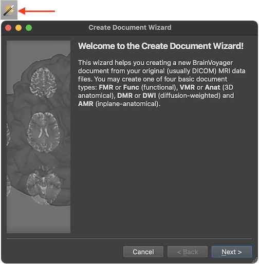
The screenshot above shows the first Introduction page of the Create Document Wizard presenting text stating that four basic document types can be created, namely functional (4D) MRI projects, called FMR in BrainVoyager, slice-based inplane anatomical documents (AMR in BrainVoyager), 3D high-resolution anatomical documents (VMR in BrainVoyager) and diffusion-weighted documents (DMR in BrainVoyager). For functional MRI data analysis, FMR and VMR are the two important document types. The creation of DMR documents is described later in this chapter as well as in chapter Diffusion-Weighted Imaging Analysis. AMR documents help to visualize the anatomy of the brain in the same slice orientations than those recorded by FMR projects but inplane anatomicals are less used nowadays than in the early years of fMRI when high-resolution 3D MRI data sets were not regularly acquired.
After clicking the Next button, the wizard presents the Document Type page that can be used to select one of the described document types in the Document Type field. When selecting a document type, the Description field describes the purpose of the respective document type. In case one wants to correct or change selections made at some point while walking through the wizard, the Back button can be used to go to an earlier stage. The Cancel button can also be used to quit the dialog without creating the document.
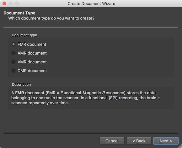
In order to create a 4D functional document from scanner files of a single run (scan) in a scanning session, the FMR document type needs to be selected in the Document type field (default). Functional fMRI data is obtained most of the time using the Echo Planar Imaging (EPI) pulse sequence. In a relatively short amount of time (usually between 1 and 3 seconds) all slices of one brain volume are scanned (volume TR). The important point of functional data recording is that the brain is measured repeatedly over time providing time course data of brain activity changes at each voxel. After clicking the Next button, the scanner data format can be selected on the Scanner Data Format page of the wizard.
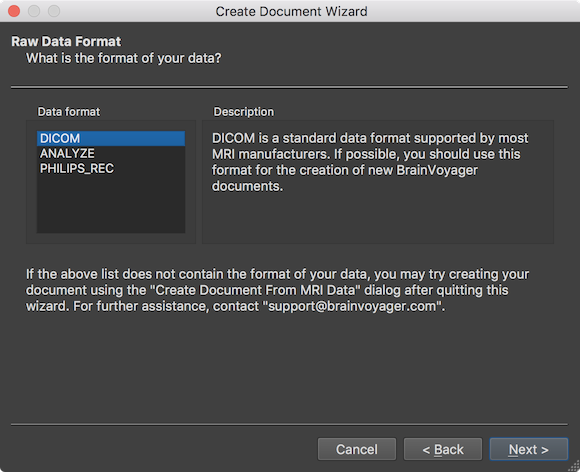
In the screenshot above, the most usual scanner data type "DICOM" is selected as default in the Data format field. The ANALYZE format was used in the early years of neuroimaging and should no longer be used since it has been superseded by the NIfTI file format. The PHILIPS_REC format is used on scanners from manufacturer Philips. It is however advised to use DICOM files also with Philips scanners, if possible. In order to select the DICOM files from which the FMR document should be created, the Select Data Location page will appear after clicking the Next button (see below).
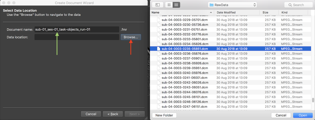
The Document name text field suggests the name "untitled" for the to-be-created functional FMR document, which should be changed. It is suggested to provide names that follow the BIDS specification as is also done when using the Data Analysis Manager to create documents.
Note. Since version 22.0 of BrainVoyager, the Create Document Wizard allows to create documents in NIfTI format and to store it in BIDS project folders. If you use this option (see below), the name should be set to the task name that will be used as part of the generated BIDS-compatible name (see below).
Since the example data used here is from the first run of the sample "Objects" experiment obtained in the first scanning session of the first subject, the name "sub-01_ses-01_task-objects_run-01" has been entered (see green arrow above). In order to select the scanned DICOM files, the Browse button on the right side of the Data location field is used to invoke a standard File Open dialog. In this dialog, any file inside the directory containing the data can be selected. In the screenshot above, a DICOM file has been selected. After selection of a file, the Open button should be clicked, which will start a process that analyzes the contents in the selected directory.
Note. In this step it is only important that the directory containing the data is selected. It does NOT matter WHICH file is selected inside that folder, which can be even a non-DICOM file. The files inside the selected folder will be analyzed and the result will be presented subsequently for the actual scanner data selection (see below).
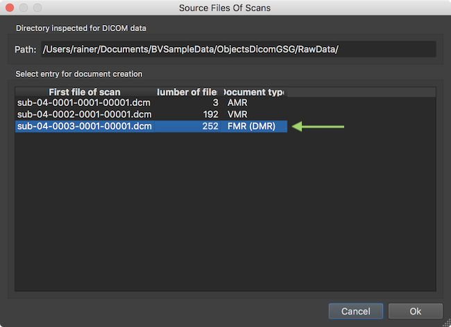
After analyzing the contents in the selected directory, the result is presented in the Source Files of Scans dialog. This dialog does not show individual DICOM files but one entry per scan corresponding to the various DICOM "series". The screenshot above shows that the program found 3 MRI series in the directory shown in the Directory inspected for DICOM data field. The program also classifies the DICOM series found according to the document type that is likely matching the respective files on disk. Here it assigns the AMR document type to the first series (actually a "scout" scan with three orthognal slice images), a VMR document and a FMR document. Since we are creatign a FMR document, the third entry needs to be selected if not done automatically.
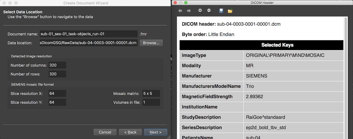
After accepting the selected DICOM series, the Select Data Location page is updated reflecting the chosen scan data by filling the Data location entry with the first DICOM file of the selected series (here 3) and by showing the dimensions of the individual slices (usually stored in separate DICOM files) in the Detected image resolution field. The program also detects that the functional data is stored in the proprietary "mosaic" format of SIEMENS and presents the actual image dimensions of a single slice in the respective SIEMENS mosaic file format field. The mosaic file format is one way to limit the number of files on disk since the slices of one functional volume are stored in a single DICOM file that can be viewed as a single image without knowing the internal structure of the data. For subsequent data analysis, the actual slice images will be extracted from the mosaic images when creating the functional document.
The program also presents a DICOM Header window showing important (but not exhaustive) fields of the extensive DICOM header from the first DICOM file read from disk. More details about how BrainVoyager uses some of these fields can be found in topic Coordinate Systems.
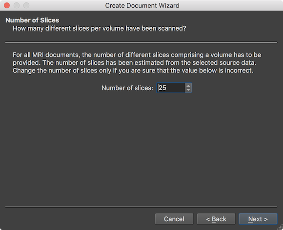
After the Next button is clicked, the wizard presents the Number of Slices page showing the number of slices that form a single functional volume (stored either in spearate files on disk, or in a single mosaic file). The value in the Number of slices field (here: 25) need not to be changed (except in case one wants to read only part of the data) and is shown for information and verification whether the number fits expectations. The page can be accepted by clicking the Next button.
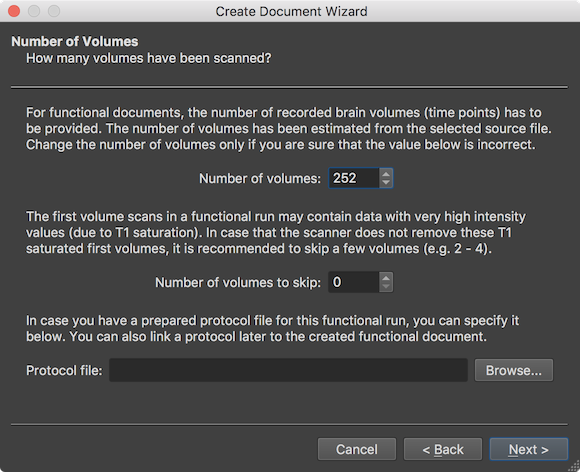
The wizard now shows data related to the repeated measurements (time dimension). The Number of volumes field shows the number of detected volumes that were scanned during the functional run (here: 292). The displayed number need not to be changed and is mainly shown for information purposes and to verifiy whether the number fits expected number. The Number of volumes to skip field allows to skip some volumes at the begin of the run in order to avoid T1 saturated volumes as detailed in the explanatory text. Usually this value should not be changed since scanners nowadays perform special "prep" scans before the actual recording to avoid this issue. Since the example data used here has been acquired more than 10 years ago, a value of 2 will be used (not shown in the screenshot but see page below) to skip T1 saturated volumes. The Protocol file entry allows to link a BrainVoyager protocol (.prt) file to the functional document, if already available at this stage. While a protocol can be added to a FMR document at any time, adding it already here is useful when creating NIfTI files (see below) and it also is useful when visualizing voxel time courses right after document creation. Consult the Getting Started Guide to learn how to define protocols using the Protocol dialog.
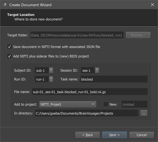
Note. Since version 22.0 of BrainVoyager, a new Target Location page is shown (see screenshot above) prior to the Summary page (see below). On the new target location page one can chose to create a NIfTI file (with associated sidecar files) as output instead of the standard BrainVoyager format. If a BrainVoyager or NIfTI output is chosen but not the BIDS option, the page also allows to specify a target folder where the created document (and associated files) are stored. As default, the directory shown in the Target folder field is the same as where the DICOM files have been found. In order to not mix the raw data location with the location of created documents, it is recommended to chose a folder that is different from the source DICOM files using the Browse button on the right side of the Target folder field. If the NIfTI and BIDS option is chosen, the created files can furthermore be named according to the BIDS standard and stored inside an existing or new BIDS project folder. These NIfTI and BIDS options are very useful since the BIDS-compatible folder hierarchy can be shared more easily with colleagues or public repositories; NIfTI files can also easily be used as the starting point for project-level data analysis pipelines with the Data Analysis Manager (see topic Import NIfTI Document Workflow). When chosing to create a NIfTI file with BIDS naming convention stored in an existing or new project folder, one needs to specify the subject, session and run to which the functional dataset belongs using the Subject ID and Session ID and Run ID spin boxes; furthermore a name for the task should be provided in the Task name field. The resulting file name is previewed in the File name text field. Futhermore, one needs to specify whether the dataset should be stored in an existing project or a new project. An existing project can be chosen from the Add to project box, which shows all projects (sub-folders) currently existing in the standard projects folder. The projects folder can also be changed by using the Select (...) icon on the right side of the In directory field. If one wants to store the NIfTI data in a new BIDS project, the New option needs to be turned on and a top-level project folder name need to be entered in the New Project text field on the right side of the New option. When all settings have been made, one can proceed to the Summary page using the Next button.
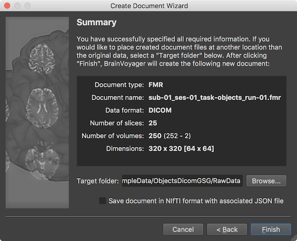
The final page presented by the wizard before creating the FMR document is the Summary page, which can be used to review the assembled and entered information. When clicking the Finish button, the functional data will be created as a FMR BrainVoyager document by assembling the individual DICOM files in a common data structrue and by storing relevant information from the DICOM header in the header of the resulting FMR file. Note that the FMR file is a human-readable text file, which links to associated data including the actual 4D voxel data stored in a STC (slice time course) file, a protocol file, if available, and additional helper filles. Note that the Summary page looks different in case one has chosen to store the data in NIfTI / BIDS format in the Target Location page (see above) and the DICOM files will be assembled and stored in a NIfTI file in the respective BIDS project folder together with a JSON sidecar file and a TSV (tab-separated value) file for the BrainVoyager protocol (if provided). If information is verified, one can proceed by clicking the Finish button.
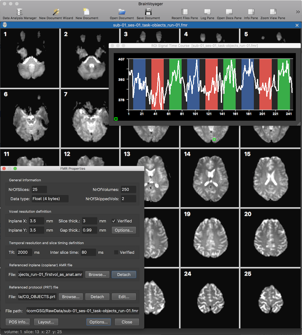
After clicking the Finish button, the functional FMR document is created and will be displayed in BrainVoyager's mutli-document area (see screenshto above showing the new document in tabbed mode). The screenshot above shows the slices (from the first functional volume) as well as the FMR Properties dialog displaying header information from the FMR file as well as providing some processing options. The displayed header information includes the number of slices in the NrOfSlices field, the number of volumes in the NrOfVolumes field as well as information about the spatial and temporal resolution of the data in the Voxel resolution definition and Temporal resolution and slice timing definition fields, respectively.
The green square in slice 9 has been created using a dragging operation with the left mouse button, which can be used to inspect the time course data of single voxels or rgions at the respective location. After releasing the mouse button, the ROI Signal Time Course plot will appear diaplaying the time course data of the selected region. The plotted curve is shown on top of a visualization of the protocol which had been linked to the document already in the wizard's Number of Volumes page (not shown above). The name of the protocol, "CG_OBJECTS", is also shown in the Referenced protocol (PRT) file field of the FMR Properties dialog.
Copyright © 2023 Rainer Goebel. All rights reserved.