BrainVoyager v23.0
The 3D Viewer
The previous topics have shown how slice-based MR imaging documents can be opened or created from original scanner data. For advanced data analysis and visualization, BrainVoyager supports the creation and processing of mesh (surface) documents that are manipulated in the 3D Viewer window - or 3D Viewer for short. A 3D Viewer can be used to open and visualize one or more mesh (SRF) documents. Since meshes are usually derived from 3D anatomical (VMR) data sets, a 3D viewer can only be opened when at least one VMR document window is available in the multi-document area. In case that a VMR document window is the currently active document, a 3D Viewer can be launched and will be associated with the currently active VMR document window and vice versa. This link extends from the respective windows to the contained documents, i.e. any mesh loaded or created in the 3D Viewer is automatically linked to the anatomical VMR document in the associated document window. The established link allows many useful analysis and visualization scenarios:
- a head mesh can be derived from the skin surface of an anatomical document.
- A cortex mesh can be reconstructed from e.g. a grey/white matter segmentation loaded in the associated VMR document window.
- A mesh can be sliced revealing the anatomical data of the associated VMR (see Mesh Slicing section below).
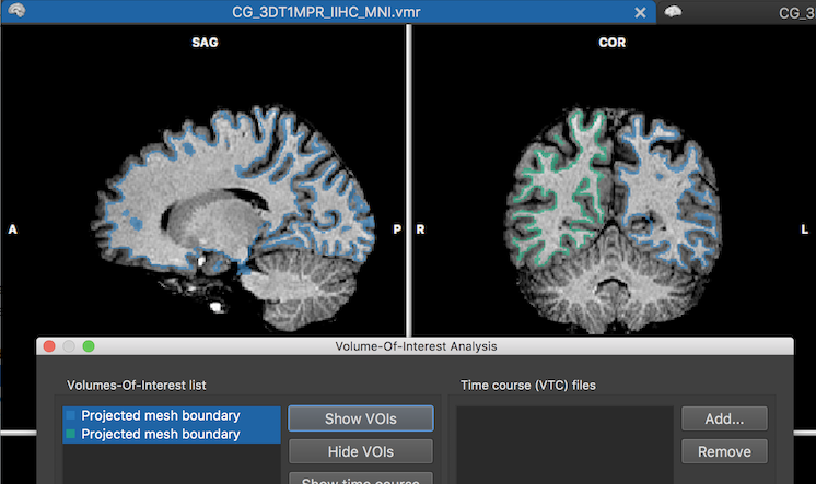
- A created cortex mesh can be projected into the VMR document loaded in the linked anatomical document window (see example below).
- A click on a mesh surface can display the corresponding position in the associated VMR document.
- A cortex mesh can create surface maps (SMPs) and mesh time course (MTC) data by sampling volume maps (VMPs) and 4D volume time courses (VTCs) loaded to the associated VMR document.
In the following sections, basic possibilities of working with meshes in the 3D Viewer will be described. More advanced features, e.g. reconstruction of head and cortex meshes, are described in specific subsequent topics, some of which are linked above and below. The 3D Viewer is also the basis of Movie Studio, a tool that can be used to produce stunning animations that can be exported as a sequence of rendered images or standard movie files.
Mesh Toolbar and Panels Master Switch
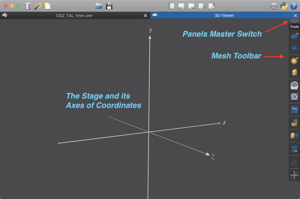
When invoking an empty 3D Viewer, e.g. by clicking the 3D Viewer button in the 3D Volume Tools dialog of a VMR document window, the 3D Viewer will only show three axes of a coordinates (see below), a welcome text that fades away quickly, and the Mesh Toolbar with title "Tools" on the right side (see snapshot below). The Mesh Toolbar allows to access major functions of the viewer and it can be freely moved around by clicking and holding its title bar. Its icons either launch a certain function of invoke a panel for controlling parameters of a specific function. Hovering the mouse over an icon reveals a tooltip briefly describing the respective function.
There is also a half grey disk at the right upper corner of the 3D Viewer, which represents the Panels Master Switch. Clicking the master switch will hide all floating panels including the Mesh Toolbar. When clicking the master switch next time, the toolbar is made visible again but not any other floating panel. Since the toolbar is then also positioned at its default location, clicking the master switch twice is a convenient way to "clean" the 3D Viewer window.
When clicking down the Panels Master Switch and holding the mouse down for a couple of seconds, the Mesh Info Text field will be toggled on and off. The Mesh Info Text field is shown in the right lower corner of the 3D Viewer and is visible as default (see snapshots below). It contains information about the current mesh (file name, number of vertices and triangles) as well as the name of the associated VMR document of the current mesh. When double-clicking the Panels Master Switch, the master switch itself will be hidden (when the mouse pointer is outside its area). This can be helpful if one wants to have a completely empty background of the 3D Viewer, e.g. when taking screensots. The Panels Master Switch can still be (temporally) shown when in hidden state by moving the mouse pointer inside its area in the right upper corner. To switch it back to visible mode, the master switch need to be double-clicked, i.e. double-clicking toggles visible vs hidden mode.
Axes, Viewpoint and the Stage
The origin of the displayed coordinate system coincides with the center of the (usually invisible Stage displaying meshes and other 3D data such as textures. The X, Y and Z coordinate axes shown as default correspond to the OpenGL coordinate system where the X axis runs from left to right, the Y axis from bottom to top and the Z axis from inside the screen towards the viewer.
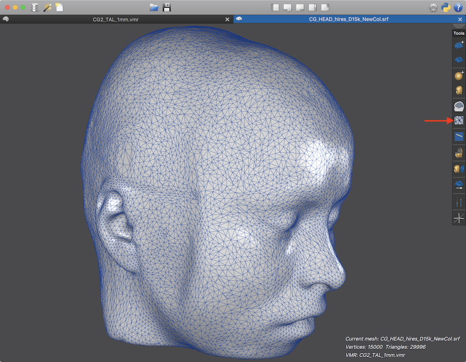
After loading a mesh it will be shown on the stage. Following the default PIL+ BrainVoyager coordinate system (but with teh Y axis flipped), the OpenGL axis can now be interpreted as a PSL+ system, i.e. the X axis runs from anterior to posterior, the Y axis runs from interior to superior and the Z axis runs from right to left.
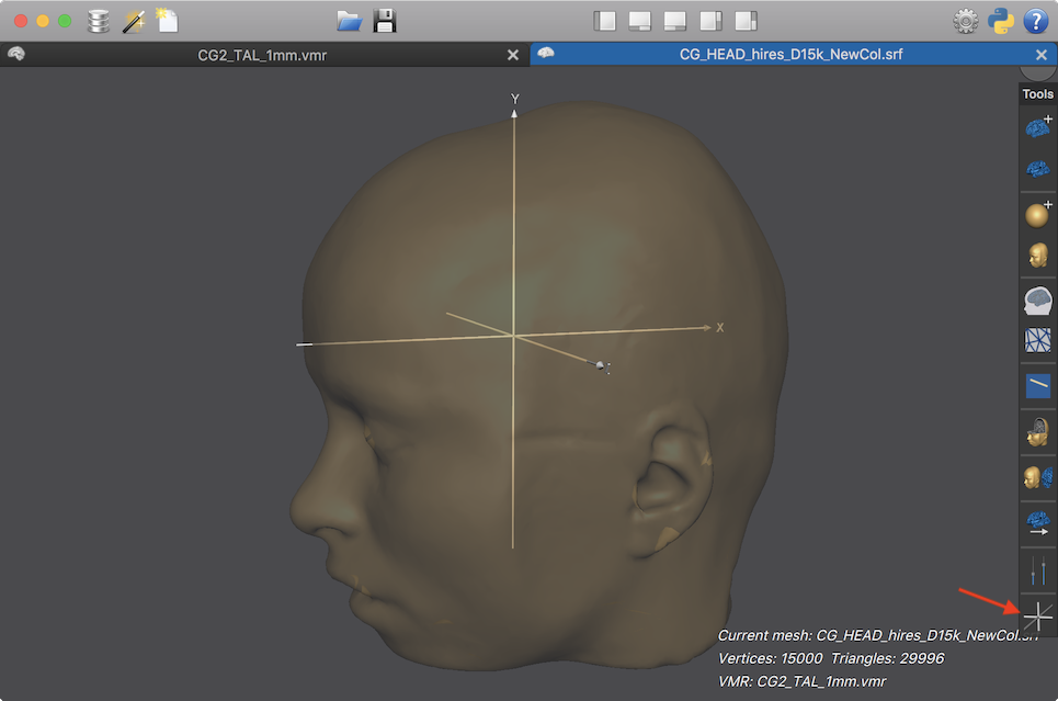
The mesh has been rendered transparent (see below) in order to allow seeing the three axes also inside the head. Since the mesh is in Talairach space, the coordinate system can be adjusted to reflect the Talairach or MNI coordinate system by clicking the OpenGL / MNI Axes icon in the Mesh Toolbar (see arrow in snapshot above). When clicking once, the MNI/TAL coordinate system is shown, i.e. the axes now correspond to the standard RAS+ system (X axis runs from left to right, Y axis runs from posterior to anterior, Z axis runs from inferior to superior) with respect to the subject's head. Clikcing once more the OpenGL coordinate axes are shown again but the axes are now colored red (X), green (Y) and blue (Z). Clicking once more, the MNI/TAL coordinate system is shown again but in red, green and blue colored axes (see snapshot below). Another click on the icon will hide the axes from view, which might be useful for taking snapshots (also in the context of Movie Studio. When clicking once more on the OpenGL / MNI Axes icon, the first display option (OpenGL, white axes) is shown again. Note that you can also press the A key to switch to the next axes state in case the 3D Viewer window is the active window accepting input.

In summary, the OpenGL / MNI Axes icon allows to cycle through 5 states:
- OpenGL white axes
- MNI/TAL white axes
- OpenGL red, green, blue X, Y, Z axes
- MNI/TAL red, green, blue X, Y, Z axes
- Axes hidden (not shown)
Viewpoint Navigation
The position and orientation of the stage, and thus all meshes on the stage, can be manipulated by either mouse and keyboard actions, by touch screen / track pad finger actions or by the Viewpoint Navigation panel (see below). Viewpoint changes are not (usually) moving the camera (that "records" the scene) but actions manipulate the position and orientation of the Stage while the camera stays at a fixed position. This approach enables constant lighting (coming from the camera position as default) and a clear and consistent way to rotate around meshes than when moving the camera.
Note. An important point is that the translation operations work on a global OpenGL coordinate system, not along the current stage/meshes axes, i.e. they operate independent of the current orientation of the stage. This will lead to a consistent behavior, e.g. performing a left translation action using the keyboard or the Viewpoint Navigation panel will always move the stage/meshes to the left. The same holds true to some extent also for rotation actions but the situation is more complex when performing combined rotations alogn multiple axes. For mouse-driven (and touch-driven) rotations there are two different rotation modes that can be set in the 3D Viewer tab of the Settings dialog (Preferences dialog on macOS). Rotating purely around global axes can be chosen by checking the Rotate around global X, global Y and global Z axis option. While this "all-rotations-around-global-axes mode" is very intuitive, it has the disadvantage that the orientation of a mesh easily changes its orientation around the local z axis, i.e. the head/brain "looks down or up" after some rotation actions. In order to prevent this, i.e. to "keep the head/brain straight", a special mode has been defined that rotates around the global X axis but around the local Y (and local Z) axis. This Rotate around global X, local Y and local Z axis mode is selected as default in the Settings dialog (this is also the mode used in pre-v21 versions of BrainVoyager).
In order to change the viewpoint of the Stage (actually the coordinate system of the stage itself), and thus all meshes on the stage, mouse and keyboard actions can be used as follows (axes referring to OpenGL coordinate system):
- X axis rotation. Clicking the left mouse button down anywhere inside the 3D Viewer window and holding the button down while moving the mouse up and down rotates the Stage around the global X axis.
- Y axis rotation. Clicking the left mouse button down and holding it down while moving the mouse left and right rotates the Stage around the local Y axis (default mode) or the global Y axis (in all-rotations-around-global-axes mode).
- Z axis rotation. Pressing and holding the ALT key when clicking down and holding the left mouse button while moving the mouse left and right rotates the Stage around the local Z axis (default mode) or global Z axis (in all-rotations-around-global axes mode). On Linux use the SHIFT key combined with right mouse button movements instead of the ALT key.
- X axis translation. Clicking the right mouse button down and holding it down while moving the mouse left and right moves the Stage to the left and right of the global X axis. With a one-button mouse (or when using only the left mouse button), combine the (one or left) mouse button with the SHIFT key, which is interpreted as a right mouse button action.
- Y axis translation. Clicking the right mouse button down and holding it down while moving the mouse up and down moves the Stage up and down along the global Y axis. With a one-button mouse (or when using only the left mouse button), combine the (one or left) mouse button with the SHIFT key, which is interpreted as a right mouse button action.
- Z axis translation. Clicking the left and right mouse buttons down and holding them down while moving the mouse up and down moves the Stage towards and away the camera along the global Z axis. With a one-button mouse (or when using only the left mouse button), combine the (one or left) mouse button with the CTRL key (CMD key on macOS) and SHIFT key, which is interpreted as a left+right mouse button action. Note that the SHIFT key must be pressed slightly earlier than the CTRL/CMD key, otherwise the key combination will be interpreted as a vertex click operation, which temporarily blocks viewpoint navigation.
With these rotations and translations any desired viewpoint can be established. Note that the Z axis rotation using the ALT key is very useful when using the all-rotations-around-global-axes mode to adjust the view after some X and Y axis rotations.
In case the 3D Viewer is the active window accepting input, viewpoint rotations and translations can also be perfromed by using the keyboard. Left / right and up / down cursor key presses perform rotation around the Y and X axis respectively. Holding down the SHIFT key, left / right and up / down cursor key presses result in X and Y translations, respectively. If both CTRL/CMD and SHIFT key is hold down, up/down key presses lead to Z translations, i.e. zooming operations. In case that another panel (e.g. toolbar) has input focus, press and release once the CTRL key to switch keyboard input focus back to the mesh scene (stage).
Touch screens and track pads. On Windows 10 with touch screens one can also use one and two finger gestures to control the viewpoint. On macOS 10.12+ the same gestures are also supported on internal and external track pads. On both systems, one finger movements are interpreted like left mouse button movement actions as described above, i.e. they rotate the Stage around the Y (left/right finger movement) and X axis (up/down finger movement). A two-finger pinch movement performs a Z axis translation, i.e. it mimicks a zooming operation by bringing the Stage closer to or further away from the camera; a two-finger rotation gesture around a virtual center point performs a Z axis rotation (corresponding to the ALT key with left-mouse button action described above); finally, a two-finger panning movement (with a fixed distance and relative position of the fingers to each other) performs a translation along the X and Y axis.
As mentioned above, the Stage viewpoint can also be changed using the Viewpoint Naviagation panel that can be invoked by clicking the Viewpoint Navigation icon (see snapshot below), which is located above the OpenGL / MNI Axes icon.
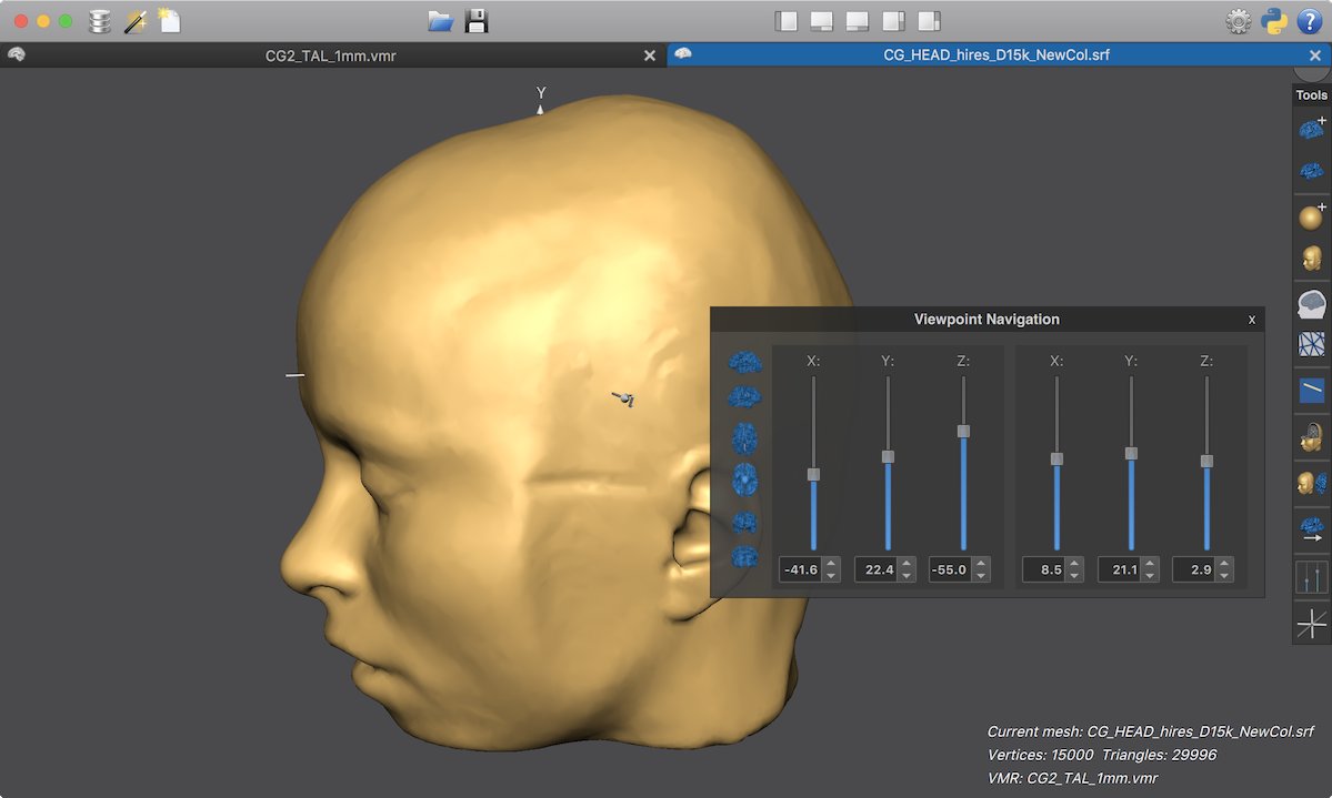
By clicking and holding the mouse on the title bar of the Viewpoint Navigation panel, it can be moved to another location but not outside the 3D Viewer window, i.e. it is embedded in that window. The same holds true for any other panel (see below) of the 3D Viewer. The left side of the Viewpoint Navigation panel shows a list of icons that, when clicked, sets the stage to a canonical viewpoint as indicated by the brain icons (from top to bottom: Left View icon, Right View icon, Top View icon, Bottom View icon, Front View icon and Back View icon). Right to the icons are 6 vertical sliders, the first three are for translating the stage viewpoint along the X, Y, and Z axis, while the sliders on the right are for rotations around the X, Y and Z axes. Note that the axis labels refer to the OpenGL coordinate system and it might thus be helpful to set the axes to the OpenGL labels (see above), especially during early experience with the 3D Viewer. When clicking the handle of the X Translation slider and then moving it up or down, the stage - and thus any mesh on the stage - will be moving to the right or left, respectively. When using the Y Translation slider, the stage is moving up or down when sliding upward or downward, respectively. Using the Z Translation slider, the stage can be moved closer or further away by moving the slider up or down, respectively. The Z Translation slider, thus, functions like a zooming-in zomming-out operation. The exact values of the X, Y and Z position of the stage with respect to the camera are available in the respective X Translation Value, Y Translation Value and Z Translation Value fields below the respective sliders. Note that you can change the viewpoint also by entering values in these boxes or use their up/down spins for small incremental changes.
When clicking the handle of the X Rotation slider, Y Rotation slider or Z Rotation slider, the Stage can be rotated around the respective global OpenGL X, Y and Z axis. When rotating around several axes, it is more difficult to predict the exact behavior resulting from changing the overall orientation of the viewpoint since the result depends also on the order of axes rotations and some experimentation might be necessary to get desired results. Like with the translation sliders, the rotation values can also be adjusted using the X Rotation Value, Y Rotation Value and Z Rotation Value fields below the sliders. Note also that the values and slider positions reflect also viewpoint changes made via mouse and keyboard in case that the panel is visible.
Loading and Saving the Stage Viewpoint
When saving a mesh to disk using e.g. the Save Mesh As or Save Mesh item in the Meshes menu, the current viewpoint will be automatically saved to disk as a simple text file with the same name as the stored mesh file but with a ".svp" (scene viewpoint) file extension. When the mesh is loaded at a later time, the respective .svp file is also loaded automatically and the same viewpoint is re-established that was present when saving the mesh. Besides automatic saving and loading, the current viewpoint can be saved at any time using the Save Viewpoint item in the Scene menu. Likewise, a previously stoed viewpoint can be loaded at any time using the Load Viewpoint item in the Scene menu. The menu access is particularly useful when one wants to save and later reload not only the scene viewpoint but also specially adjusted local coordinate systems of multiple meshes, since mesh local coordinate systems are also stored in a scene viewpoint file (see below).
Multiple Meshes and the Current Mesh
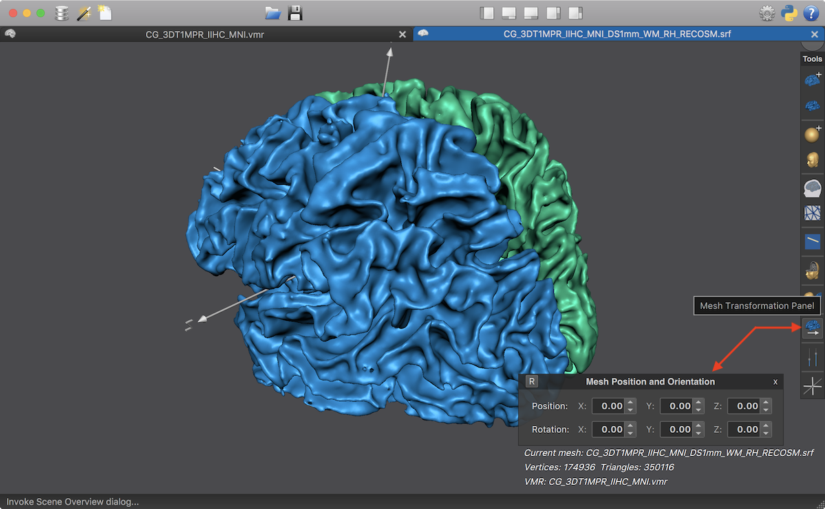
While changing the viewpoint of the Stage is usually enough to achieve a desired view on the scene, it is also possible to change the position and orientation of meshes relative to the stage. This is useful when one wants to present meshes in a specific relative layout with respect to each other, e.g. showing separately reconstructed left and right hemisphere cortex meshes side by side in a specific layout as will be demonstrated below. For handling multiple meshes, it is important to realize that mesh-specific functions operate on the current mesh, i.e. the mesh that has "focus". In the snapshot below, two meshes have been loaded, one representing the left and one the right cortical hemisphere. In order to distinguish the two meshes easily, their color have been changed to a blue (left hemisphere mesh) and green (right hemisphere mesh) color tone. The last mesh added to the scene using e.g. the Add Mesh item in the Meshes menu will automatically become the current mesh.
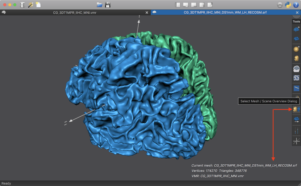
In order to switch focus from one mesh to another, an easy way is to click the Select Mesh / Scene Overview Dialog icon in the Mesh Toolbar (see red arrow in the screenshot above). A click on the icon will advance focus to the next mesh in an internal order to become the new current mesh. The new mesh can be identified by its name in the Mesh Info Text field displayed in the right lower corner of the 3D Viewer window (see arrow above). In the example scene loaded above, the name will switch between the left (containing the "_LH_" substring) and right (containing the "_RH_" substring) mesh name. Any mesh operation executed now will be using the current mesh. To change, for example, the background color for each mesh, the Background and Curvature Colors dialog can be used (that can be invoked using the Background and Curvature Colors item in the Meshes menu) once for the left and once for the right hemisphere mesh, as has been done in the example above.
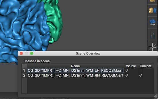
When one has more than two meshes, it might be more convenient to use the Scene Overview dialog (see screenshot above) to select the current mesh from a list. This dialog can be invoked by SHIFT-clicking the Select Mesh / Scene Overview Dialog icon or by using the Scene Overview item in the Scene menu. The Scene Overview dialog shows the order that BrainVoyager uses to refer to the meshes internally in a table displaying the name of each mesh in teh Name column. The most right Current column indicates which one of the multiple meshes is set as the current mesh. By simply clicking in the Current column of the row of another mesh, it can be made the new current mesh. This will also be reflected in the Mesh Info Text field in the 3D Viewer. Note that the Scene Overview dialog can also be used to show or hide selected meshes by toggling the check mark fields in the Visible column.
Mesh Position and Orientation
In case one wants to create specific scene layouts when working with multiple meshes, the position and orientation of the current mesh can be changed relative to the Stage viewpoint using the Mesh Position and Orientation panel that can be invoked by clicking the Mesh Transformation Panel icon in the Mesh Toolbar (see screenshot below). The Position X, Position Y and Position Z value fields allow to view and change the origin of the current mesh's coordinate system, while the Rotation X, Rotation Y and Rotation Z value fields allow to view and change its orientation. Besides entering values directly as text, the up and down spins of these fields can also be used to perform small incremental changes. Note click and hold down an up or down spin to execute the respective incremental change repeatedly. Also note that in contrast to the viewpoint, the position and orientation changes work in the local (OpenGL) mesh coordinate system so that e.g. a change in the X axis will move the mesh forward or backward along its local X axis independen of the orientation of the Stage.
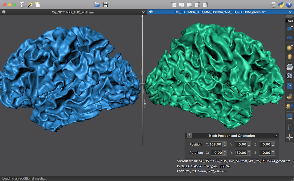
The snapshot below shows a scene that contains the same meshes as above but with modified local coordinate values presenting both hemisphere meshes from a lateral view (or medial view when rotating the Stage viewpoint by 180 degrees around the Y axis). This layout might be, for example, useful to present overlaid functional results on both hemispheres when preparing figures for publication. The Mesh Position and Orientation panel in the screenshot below shows the specified position and orientation values for the second (right hemisphere) mesh revealing a shift along the X axis and a 180 degree rotation around the local Y axis while the first (left hemisphere) mesh received only a position change (value 110 for position X) but no rotation.
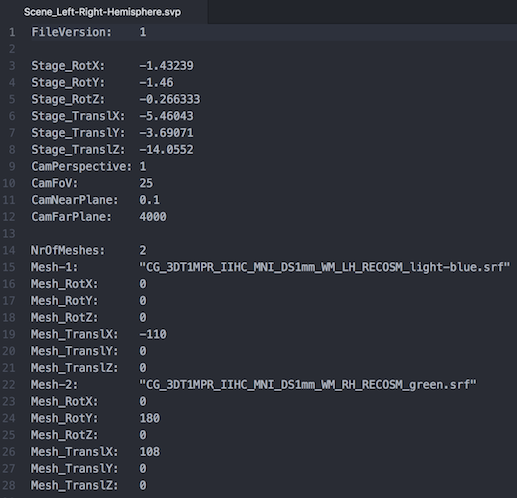
An established layout for multiple meshes can be saved to disk for later use by using the Save Viewpoint item in the Scene menu as described above since a scene viewpoint (.svp) file not only stores the viewpoint of the stage but also the local coordinate system of all meshes contained in the scene. When such a multi-mesh viewpoint file is reloaded at a later point, the local coordinate values are applied to the meshes in the scene but only if the mesh file names in the scene viewpoint file match to the names of the meshes currently in the scene. The snapshot below shows the .svp file stored for the arrangement of the two meshes depicted above.
Note. Like stage viewpoint changes, specifying positions and orientations for individual meshes does not affect the spatial link of the mesh with the "hosting" VMR document since these local coordinate changes are not implemented by changing the values of the mesh verex coordinates. This can be, for example tested by projecting the positions of mesh vertices into the VMR document (using the Mesh -> VMR button in the Mesh Spatial Transformations dialog, for details see topic Project a Mesh in a VMR) before and after the mesh-specific positions and orientations have been changed. The result will be the same (see screenshot below) as long as the values of the mesh vertices are not changed themselves.
Mesh Slicing
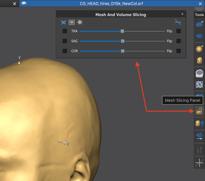
The 3D Viewer allows to slice meshes along axial, coronal and sagittal planes corresponding to the XY, XZ and YZ plane in the MNI coordinate system. Slicing can be controlled using the Mesh And Volume Slicing panel, whcih can be invoked by clicking the Mesh Slicing Panel icon in the Mesh Toolbar (see screenshot below).
The main section of the panel contains three rows with items controlling one of the three slice planes, i.e. axial (TRA, transversal), sagittal (SAG) and coronal (COR). In order to turn on or off one or more slice planes, the respective option boxes on the left side of the TRA, SAG or COR slice label can be clicked to (un-)check the respective slice plane (see screenshots below). At the sliced mesh plane, the values of the associated anatomical VMR document will be shown, i.e. the anatomical intensity values, eventually with overlaid functional map data in case a volume (VMP) map has been loaded. The mesh can be sliced on one of two sides. The Flip option boxes on the right side of the panel can be used to determine which half of the mesh should be cut away, e.g. for an axial slice, either the upper part or the lower part of the slice level can be removed from the mesh. In order to change the level of a slice plane, the TRA slider, SAG slider or COR slider can be used.
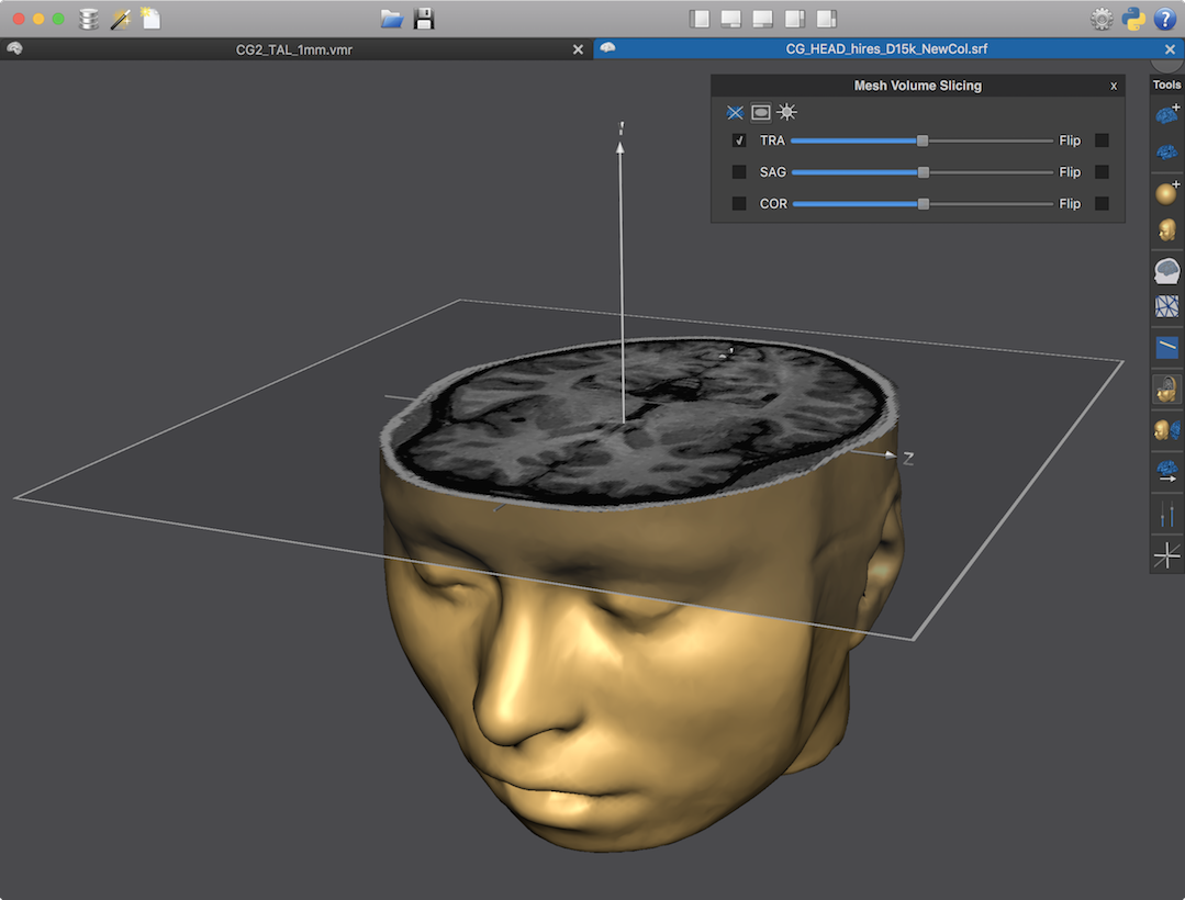
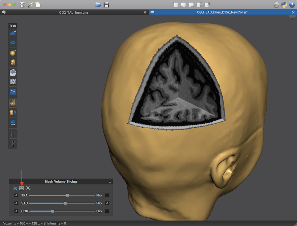
The snapshot above shows a loaded head (skin) mesh after turning on the axial slicing in the Mesh And Volume Slicing panel. One can see the intensity values of the associated VMR document. Note that the VMR document has intensity value 0 in background voxels (outside the head), which are rendered transparently resulting in a nice visualization limiting the displayed VMR data to head/brain voxels.
Note. The inside head/brain low-intensity voxels will likely be shown also transparent, which may not be desired. In order to render low-intensity voxels inside the head black but not transparent (as shown in the screenshot above.), the filled-volume mesh projection tool can be used.
In the screenshto above, a transparent sliciing frame is shown with a white border outside the head in order to highlight the slicing operation. In order to change the slicing level, the TRA slider can be moved to the left (slicing down) or to the right (slicing up). Note that the intensity values from the associated VMR document are updated immediately when gradually slicing up or down and the slider shows a tooltip revealing the slicing level of the VMR document.
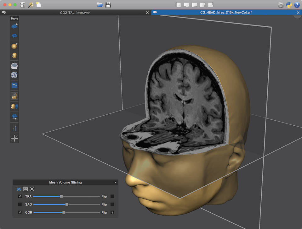
In the screenshot above both transversal and coronal slice planes have been turned on. The Flip option box has been checked for the COR slice plane in order to remove the anterior part of the mesh. Note that the two slice planes are combined removing only the joint part of the mesh that is above the axial slice plan and in front of the coronal slice plane. In the screenshot above, the Mesh And Volume Slicing panel as well as the Mesh Toolbar have been moved to the left side of the viewer just to demonstrate that all panels are floating palettes.
The screenshot above shows combined transversal, sagittal and coronal slicing. Note that only the intersection of the three slice partitions is removed from the mesh with nice cut outs (this was not possible before version 21 of BrainVoyager). In this example the transparent slicing frames have been removed by clicking the Slice Framing icon in the Mesh And Volume Slicing panel (see red arrow above). On the right side of this icon is the Constant Slice Brightness icon (looking like a sun symbol), which can be used to illuminate all slice planes with a constant bright light that does not depend on angle of a slice plane to the light direction of the default scene light shining from the front (camera position) into the scene. The Hide Mesh icon on the left side (crossed out mesh symbol) can be used to show only the full crossed enabled slice planes without the mesh, which might be useful for specific visualization scenarios. Note that these icons are toggles, i.e. repeatedly clicking them will turn on or off the respective function.
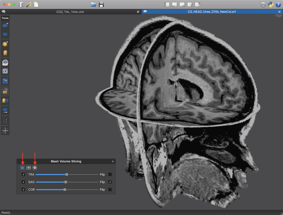
In the screenshot above, the mesh has been hidden revealing all three slice planes. Furthermore, constant slice lighting has been enabled (see red arrows above). The slice frames have also been turned off, which is recommended since smultiple slice planes without a mesh might not always render transparency through slides as expected.
Oblique Slicing
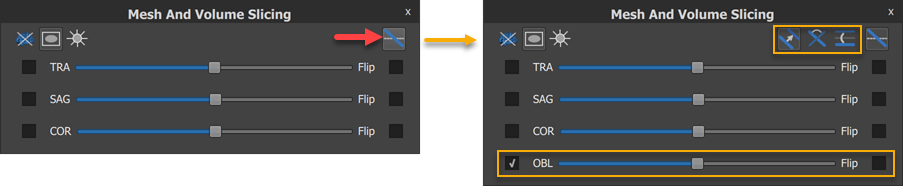
Since BrainVoyager 21.4 an additional slice can be added that can be freely oriented, i.e. it is not limited to orthographic slice positions. In order to reveal the respective options, the Show and Manipulate Oblique Slice icon can be clicked (see red arrow in left pane of screenshot above). At the bottom of the panel, a new row with elements appears to show hide or flip the OBL (oblique) slice in the same way as the other slices. The slider, however, implements not just one but three different slice manipulation options that depend on the icon selected in the right upper field (see orange rectangle in right upper position above). If the Move Oblique Slice Along Plane Normal icon (left one) is selected (default), the oblique slice will be moved along its plane normal in the same way as the other slices. If the Rotate Oblique Slice Around Z Axis icon (middle one) is selected, the OBL slider rotates the slice around the Z axis. Finally, if the Rotate Oblique Slice Around X Axis icon (right one) is selected, the OBL slider rotates the slice around the X axis. By combining the three manipulation options, the orientation and position of the oblique slice can be adjusted as desired.
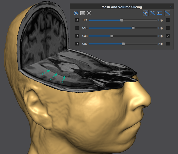
The screenshot above shows an example usage of the oblique slice in combination with a transversal and coronal slice. The oblique (near axial) slice is placed to follow the hippocampi in both hemispheres (green arrows point to hippocampus in right hemisphere).
Wireframe Rendering
In some situations (e.g. to check the quality of cortex reconstructions) it is useful to inspect the underlying wireframe of a mesh - vertices and their connections - instead of a smoothly shaded mesh. The Wireframe Rendering icon in the Mesh Toolbar can be used to switch to wireframe rendering mode (see snapshot below). Another click on the icon returns to normal rendering. Note that the wireframe is shown on top of a rendered full mesh (slice levels are ignored) with a white background color since local geometry is difficult to inspect when seeing wires from multiple front and back sections of a transparently rendered mesh. Wireframe rendering without a shaded mesh may, however, also be used for a simple transparency effect, i.e. to look through a wireframe head onto a shaded brain and such an option will be added to the 3D Viewer (but see below fortransparency rendering of shaded meshes).
Shininess and Transparency
The Mesh Transparency and Shading Options panel can be used to manipulate the shininess of a mesh and to render a mesh more or less transparent (see below). The panel can be invoked by clicking the Transparency / Shininess Panel icon in the Mesh Toolbar (see red arrows in snapshot below).
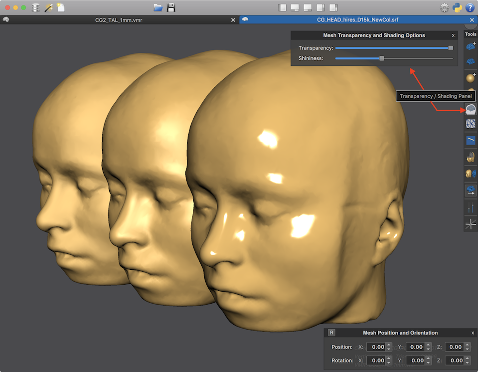
In the screenshot above, the same head mesh has been loaded three times in a 3D Viewer window and shifted along the (OpenGL) Z axis using the Mesh Position and Orientation panel to get a side-by-side view of the meshes. The head mesh in the middle shows the default shininess rendering (value 6) that is also indicated by the position of the Shininess slider in the Mesh Transparency and Shading Options panel. The mesh on the left has been rendered with lowest shininess (value 1), i.e. the slider has been moved completely to the left side after making this mesh the current mesh. The mesh on the right side on the other hand has been rendered with the highest shininess value (100) by moving the slider completely to the right side. While shininess is not a very important feature, this option allows to adjust shininess to the taste of a user e.g. when preparing figures for publications.
The screenshot above shows a transparent rendering of the head mesh that has been created by moving the Transparency slider of the Mesh Transparency and Shading Options panel to the left. This reveals a second brain mesh that has been added to the scene. For further visual effects, axial and coronal slicing of the head mesh has been enabled also revealing the second brain mesh.
The scene above shows 4 3D objects, a transparent head mesh, a brain mesh as well as two textured planes with transparent framing slices. Note that is challenging to get transparency right in case of multiple meshes and BrainVoyager tries to solve this by adjusting the order of mesh rendering. This can be supported by loading "inside" meshes before "enclosing" meshes. In the scene above it is, for example, recommended to load the brain mesh first followed by the head mesh. A more advanced (but slower) transparency rendering strategy is planned as an additional option for a future release.
For more advanced uses of the 3D Viewer, check topic Overlaying Surface Maps in the Statistical Data Analysis chapter, Head Skin Reconstruction and Reconstructing Edited Brain Volumes in the Segmentation chapter and Drawing POIs in the Useful Tools chapter.
Copyright © 2023 Rainer Goebel. All rights reserved.