BrainVoyager v23.0
Projecting a Mesh as Filled Volume
The previous topic described how a mesh can be projected in a associated VMR. In this process voxels (ntegral coordinates) closest to mesh vertex positions (floating point coordinates) are marked either directly in the VMR volume or via a VOI overlay (default). For some applications (see below for an example) it would be useful to not only obtain a contour along the mesh but a representation where the interior of the contour is filled. Such a filled representation can be used, e.g. as a mask for some operations or to project a segmented brain mesh to a higher or lower resolution than the original one from which the mesh was created. An obvious way to fill a projected contour in a VMR would be to use the standard region growing tool available in the 3D Volume Tools dialog. Unfortunately the projected contour is often not dense enough and region growing will often bleed outside the contour, e.g. when projecting and fillng a head mesh.
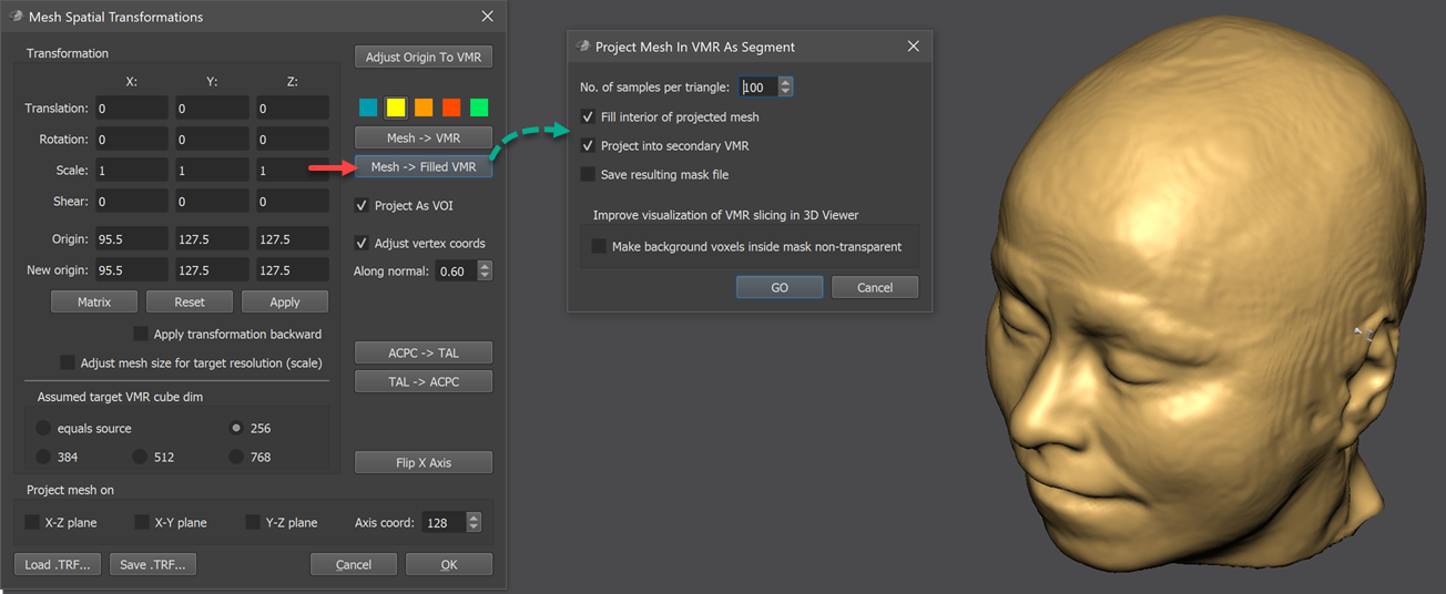
In order to support creation of filled mesh projections, a special tool is available since BrainVoyager 21.4 that creates closed contours in a VMR as long as the mesh itself is a closed surface. The tool can be launched by clicking the Mesh -> Filled VMR button in the Mesh Spatial Transformations dialog (see red arrow in screenshot above). The appearing Project Mesh In VMR As Segment dialog (see green arrow above) provides options to control the projection process. The No. of samples per triangle field can be used to specify how many sub-sampled positions should be generated inside each mesh triangle for VMR projection. The default value of 100 is very high and should lead to closed contour projections for regular head and brain meshes. The default high-density triangle sub-sampling will generate 100 positions inside mesh triangles that will result in redundant markings of voxels, i.e. the same voxel will be "hit" by many mesh positions. Since the process operates in a few seconds, this can be accepted with the benefit that a closed contour is ensured even in cases with triangles that may be stretched during a morphing operation. In cases where projected contours are nonetheless not closed, the number of samples per triangle can be increased up to a value of 1000; on the contrary, computation time can be saved by lowering the value down to a minimum value of 10 but this will increase the risk of creating contours with holes in the VMR. While the projected mesh is filled as default, one can also project only the (closed) contour into the mesh by unchecking the Fill interior of projected mesh option. Since the projection is not performed into a VOI overlay but directly written in the VMR, the projection is not done into the primary VMR - usually containing the (preprocessed) MRI intensity values - but into the secondary VMR that is created or cleaned (if already existing). In case one wants to draw inside the primary VMR, the Project into secondary VMR option needs to be turned off; note, however, that the contents of the VMR will be cleaned before projection. The resulting file (in case it is projected into the secondary VMR) is saved to disk in case that the Save resulting mask file option is turned on (default: off); the name of the resulting VMR file will be based on the name of the projected mesh file with an added substring "[mesh name]_projected_filled.vmr". In the example dataset used in the screenshots a head mesh with the name "head_hires.srf", which will lead to a saved VMR file with the name "head_hires_projected_filled.vmr".
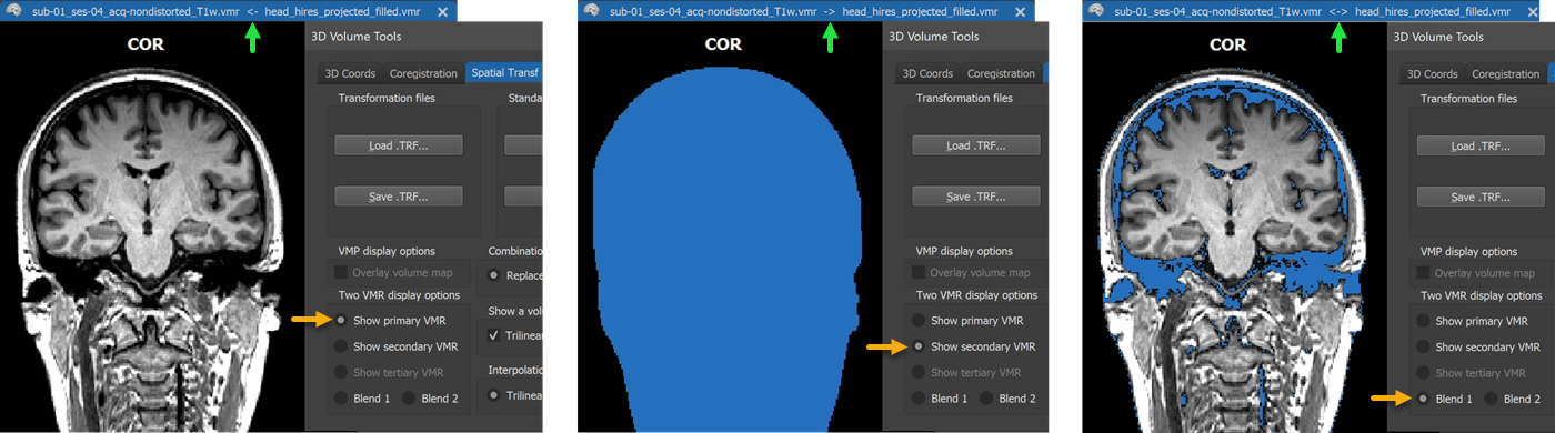
When running the dialog with default options, the created filled mesh contour will be shown in the second VMR. In order to show it, the F8 toggle can be pressed or the Show secondary VMR option can be clicked in the Spatial Transf tab of the 3D Volume Tools (see middle panel in figure above). The green arrow in the panels highlights the indicator that is shown between the name of the primary and secondary VMR pointing to the left side if the primary VMR is shown, pointing to the right side if the secondary VMR is shown, and pointing to both sides in case that a blending mode has been selected. When clicking the Blend 1 option, the voxel intensities of the secondary VMR are shown at those voxel coordinates where the primary VMR contains intensity values of zero (see panel on the right).
Enhancing Mesh-VMR Slicing Visualization
Note that the blue regions shown above in blend-1 mode will be shown transparent when slicing the mesh in the 3D Viewer, which may produce suboptimal results since one can see through displayed slices at those positions (see red arrows in left panel in figure below). The Make background voxels inside mask non-transparent option in the Project Mesh In VMR As Segment dialog provides an application of the generated mask volume that improves the VMR slicing visualization in the 3D Viewer by making black voxels of the original volume inside the projected mask non-transparent while keeping black voxels outside the mask transparent.
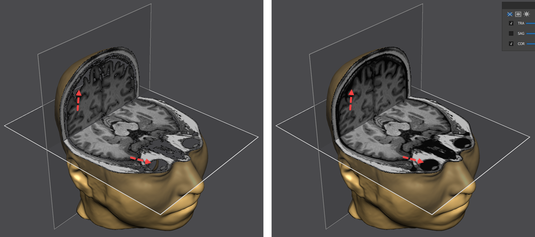
The figure above shows alicing of the example head mesh before (left) and after (right) running the projection tool with the Make background voxels inside mask non-transparent option turned on. The red arrows highlight some regions that are rendered transparent on the left side but non-transparent (black) on the right side. If one wants to keep the result of this application for later use, the primary VMR should be saved to disk.
Rendering black voxels inside of the head non-transparent is achieved by calling the standard value range mapping function (available in the 3D Volume Tools dialog) to change intensity values in the range 0 to 10 - rendered transparent in the 3D Viewer - to value 11 that is rendered as non-transparent black. The important point is that this range function is restricted to the voxels inside the created mask in the second VMR (any value larger than zero is belonging to the mask). Restricting the range function to a mask stored in the secondary VMR can also be performed manually by turning on the 2nd As Mask option in the Segmentation tab of the 3D Volume Tools dialog before clicking the Range button.
Copyright © 2023 Rainer Goebel. All rights reserved.