BrainVoyager v23.0
Generating Binary Stimulus Frames
While the pRF approach can be used with conventional ring and wedge patterns as stimuli, this method may also use other stimulus types such as bars presented at different positions and in different orientation (and width). It is also possible to use both conventional and bar stimuli in the same experiment, usually in separate runs. Note, however, that even ring and wedge patterns need not to be shown in a strictly periodic fashion as in conventional retinotopic mapping - the only important requirement is that employed stimuli are sufficiently rich to constrain the estimation of position as well as size of the population receptive field for visually responsive voxels.
The pRF method requires more detailed information about the stimulus sequence than in a conventional stimulus protocol since the modeled receptive fields need to be able to calculate the response strength at any moment in time. Since the model parameters (position and size) are estimated in degrees of visual angle, knowledge needs to be available about how a subject actually has perceived the stimuli in the scanner, i.e. it is important to know how much degrees of visual angle correspond to the extent of the used physical stimuli. The mapping from stimulus pixels to visual angle allows to calculate the location of a specific stimulus in the same coordinate system (degrees of visual angle) as the parameters of the receptive field model.
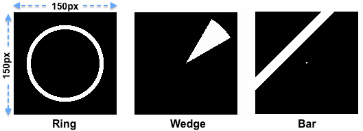
The pixel-level representation of the stimuli needs to be available in a binary stimulus time course (.stm) file that contains a representation of the stimulus at each measurement time point, i.e. for each TR of the fMRI data. A single stimulus frame contains an entry of "1" (stored in a byte) for positions that are stimulated and an entry of "0" for non-stimulated regions. The x = 0 and y = 0 pixel in the image itself must be located in the left upper corner with the x axis going from left to right and the y axis going from top to bottom. While not strictly necessary, it is recommended to use square images. In the examples shown above, the images consist of 150 pixels in each dimension. In order to reduce calculatin time during the subsequent model time course generation process (see below), it is recommended to downscale images in case they are originally generated in high resolution. This representation in the binary stimulus frames will likely be simpler as the actual stimuli used during the experiment since it abstracts from finer details within a stimulated region; if for example a classical wedge stimulus is used, it usually contains flickering elements within a wedge (to optimally drive neurons in early visual areas) but these details must not be contained in a binary stimulus frame of a .stm file. The figure above shows three example frames used at specific moments in time in three different experimental runs; the white regions in these "stimulus energy" frames indicate for one time point (one TR) which part(s) of the display area were stimulated and which not.
BrainVoyager allows to create the .stm file from individual image frames or from special files containing all stimulus frames per run. These files are generated automatically if the open source stimulus presentation software StimulGL is used that has been started by Rainer Goebel (Brain Innovation, Maastricht University) and is now mainly developed by Sven Gijsen (Maastricht University). The software as well as prepared retinotopic / pRF experiments are freely available and can be directly used to run retinotopic / pRF experiments. If other stimulus presentation software is used, the created stimulus frames need to be saved as .png files to disk (one per time point, i.e. once per TR) and BrainVoyager will build the .stm file from provided .png image files.
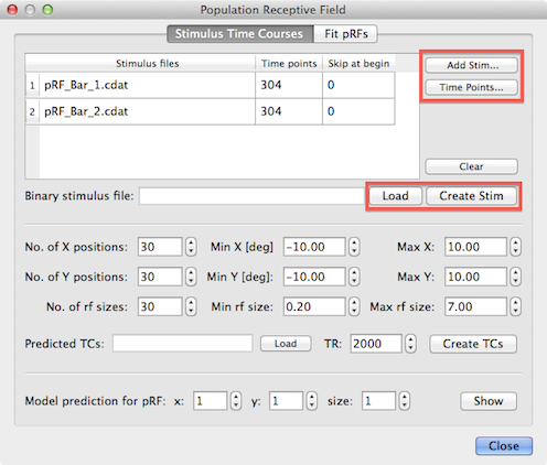
Note that BrainVoyager creates a single binary .stm file including all stimulus frames for all runs included in a pRF analysis. Each row of the Stimulus Frames table at the top of the dialog refers to the stimulus frames of one run. Note that the order of the included stimulus run data is important and must match the order of functional time course (VTC or MTC) files entered later for the actual model fitting routine in the Fit pRFs tab. You must use the Add Stim button to add a reference file name for the stimulus data of each run. The selected file name will be inserted in the Stimulus files column of the next available row in the table. If you use BrainStim (StimulGL) and select a .cdat file, BrainVoyager will fill also the Time points column with the number of stimulus frames recorded in the .cdat file. NOTE: The .cdat format is NOT supported in 2.8.x versions of BrainVoyager QX - these files will be enabled in the next major update of the software. If you use single frame data files (.dat from StimulGL or .png created with other software), the program uses that file only as a reference and will internally replace the frame number at the end of the file name with an increasing number (0, 1, 2...) to access the individual stimulus frame (.dat or .png) files. Note that the frame numbers must start at "0", i.e. the first file must end with a "_0" (plus file extension) string. When using .png files exported frome BrainStim, the files may have the string "_Scaled" appended after the file number - this string will be automatically ignored. When providing a series of individual frame (.png or .dat) files, the number of frames needs to be entered in the Time points column for each run (see below).
Note that it is important that the value in the Time points column matches the actual number of time points in the corresponding functional MRI time course (VTC or MTC) file; while this is usually the case, it is also possible that some initial volumes have been skipped when the original FMR project had been created. In that case the number of stimulus frames might be larger than the actual number of time points in the corresponding fMRI time course file. In order to ensure that the correct number of time points is used, it is recommended to use the Time Points button; after clicking this button (and ensuring that an entry of the correct row is selected), a standard file selection dialog will appear. After selection of the VTC or MTC file containing the functional data for the respective run, the Time points column in the Stimulus Frames table will be filled with the correct value that is obtained from the VTC / MTC header. If this number is the same as the number of stimulus frames, no further action is required. If the value is smaller than the number of stimulus frames, the user likely has skipped some time points during project creation. In that case check and eventually correct the number of skipped volumes in the Skip at begin column (but do not change the VTC / MTC retrieved number-of-time-points value). If you enter a non-zero value in the Sip at begin field, the program (v2.8.4 and above) will skip the first files, e.g. if the skip value is "2", the program will start reading the stimulus data with a file endign with the "_2.png" (or "_2.dat") substring instead of "_0.png" (or "_0.dat"). In older program versions (v2.8.0 and v2.8.2), the program always started reading stimulus files from frame number "0", no matter how many files have been skipped. In any case, it is important to realize that the number of stimulus frames in the Time points column matches the number of time points of the corresponding VTC / MTC file. Note that so called preparatory scans ("prep scans") are not meant by the term "skipped volumes". In case that prep scans are performed it is usually not necessary to skip volumes.
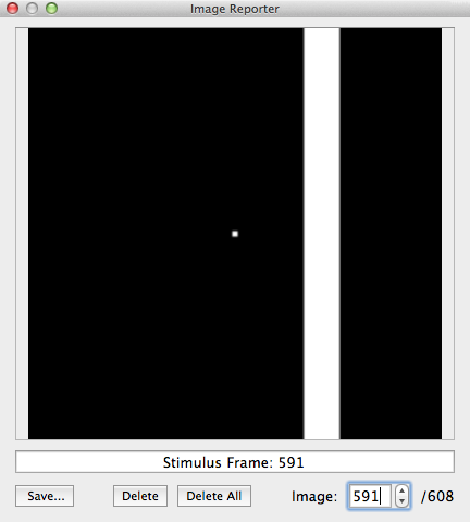
After the stimulus data for all runs have been entered in the Stimulus Frames table, the binary .stm file is produced after clicking the Create Stim button; the program asks for a name that should reflect the included runs of the pRF experiment. In the example data described here, the file has been named "Bars-1_Bars-2.stm" reflecting that the stimuli of two runs were used that presented bars at different positions and orientations. Note that a created .stm file can be reloaded later. After creating or loading a .stm file, BrainVoyager presents the binary stimulus frame in the Image Reporter. In order to interact with that tool, you need to close the Population Receptive Field dialog. The snapshot above shows the Image Reporter with a selected frame (# 591) of the generated binary stimulus frame sequence. In the right lower corner it is indicated that the stimulus frame movie contains 608 frames, i.e. the sum of the stimulus frames from the two runs each having 304 time points.
If the binary stimulus file has been created, pRF model time courses can be calculated that are needed for the pRF fitting process.
Copyright © 2023 Rainer Goebel. All rights reserved.