BrainVoyager v23.0
Drawing POIs
Like Volumes-Of-interest (VOIs) are importan for region-of-interest analysis in volume space, Patches-Of-Interest (POIs) are important for region-of-interest analysis in surface space. While there are functions that produce POIs automatically (e.g. form functional clusters), it is often useful to be able to define POIs by drawing directly on a mesh surface. The 3D Viewer offers a tool to define POIs by drawing that is invoked by clicking the Draw / Cut Mesh Mode icon (see screenshot below). The icon's name includes the word "Cut" because the tool is not only used to draw on the mesh to define POIs but also to draw cuts in a mesh, which is, for example, useful in the context of creating cortical flat maps.
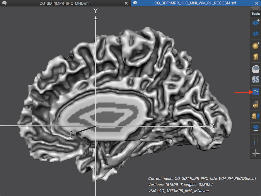
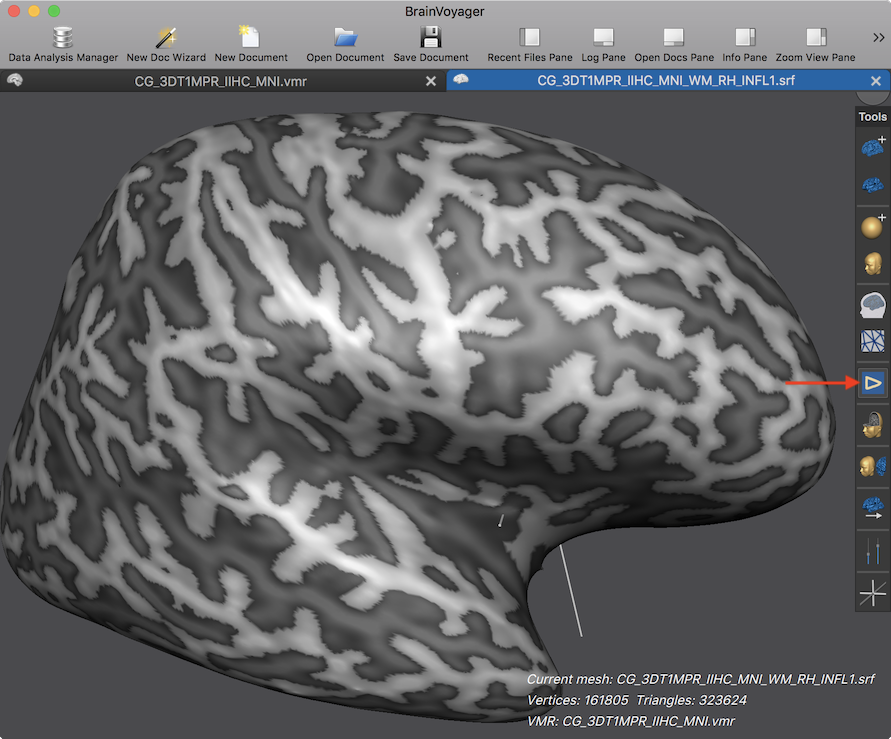
The screenshot above shows a loaded (right-hemisphere) cortex mesh. Because of the folded nature of the cortex, it is difficult to draw precise regions in this state. It is thus recommended to (partially) inflate the cortex mesh (e.g. by checking the Inflation Mode option in the Mesh Morphing dialog) or to load an already existing inflated version of the reconstructed cortex mesh. The screenshot below shows an inflated version of the mesh shown above with a few on the right side.
Basic Features
After clicking the Draw / Cut Mesh Mode icon, the 3D Viewer is put in POI drawing mode, which is indicated by the icon shown pressed in and by showing a drawn triangle instead of a line. Showing a modified icon is done just for the purpose to more easily recognize that one has entered drawing mode. When referring to the CTRL key below, it refers to the CMD key on macOS.
While mouse clicks and movements can still be used to navigate the viewpoint, e.g. to zoom close on a target region, drawing is perfomred by pressing and holding down the CTRL key and by clicking on the mesh. A single click will draw a point, which actually selects the nearest mesh vertex and sets its color to the current drawing color (see below). Holding down the CTRL key while performing a series of clicks can be used to draw a connected contour on the surface.
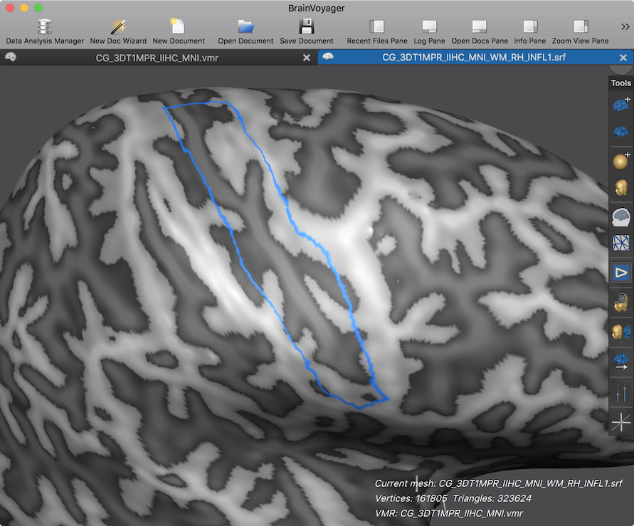
In the screenshot above, for example, a number of clicks have been made to roughly outline a major part of the central sulcus while holding down the CTRL key. This contour could be converted now in a POI but it is often desirable to define filled regions as POIs. This can be done by pressing and holding down the CTRL key in combination with pressing and holding down also the SHIFT key as a second button. When then clicking inside the closed contour, the interior is filled. The screenshot below shows the resulting filled area in the example case after CTRL+SHIFT clicking inside the contour shown above.
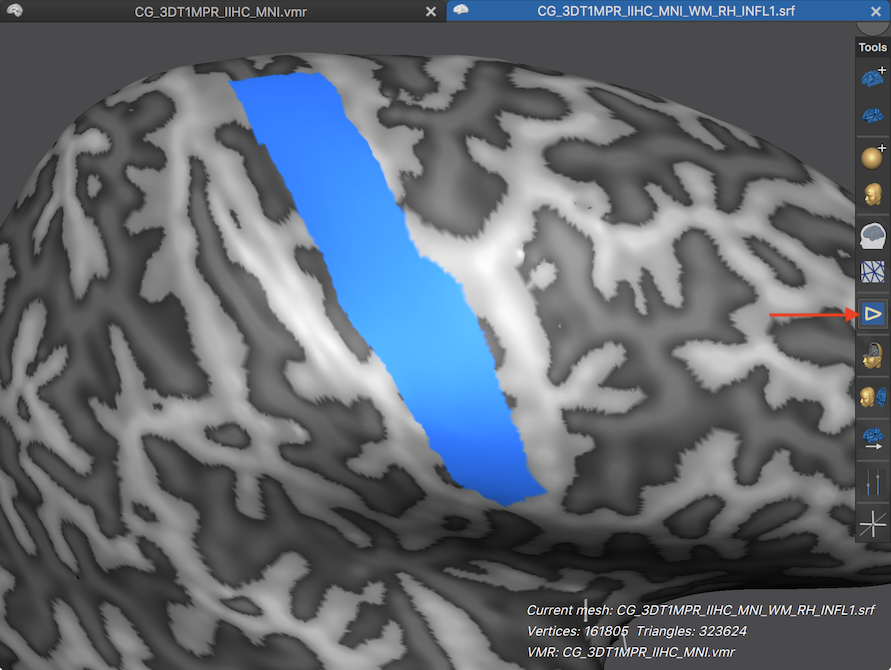
Note that in case the contour is not closed, the whole mesh will be filled with the current drawing color and one would have to correct the contour (see below). In order to convert the drawn area into a POI, simply click the Draw / Cut Mesh Mode icon to end drawing mode. This will reset the icon to its unchecked state (see circle in screenshot below) and also automatically launches the Define Patch-Of-Interest (POI) dialog dialog (see screenshot below).
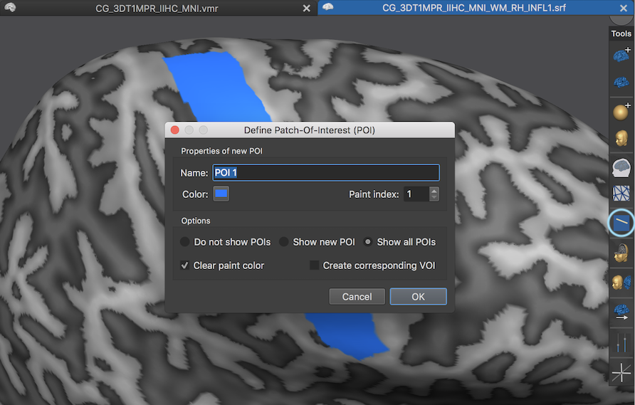
The dialog presents a default name in the Name text field for the newly defined POI ("POI 1"), which can be changed to something more expressive (e.g. "Central Sulcus" for the example case). The Color button shows the current color, which can also be changed by clicking the button. The Paint index is set to 1 and corresponds to the drawing color 1. If drawings with multiple drawing colors would exist on the mesh, the Paint index can be used to select which drawing should be used to dfine the POI. There are also a number of options determining whether the newly defined POI should be shown as a an overlay or not. The Do not show POIs option would not show any POI after the current (here first POI) is defined; the Show new POI option will show the new POI after accepting its definition but not any other POI, which might already been defined; the Show all POIs option (default) will show the new and any previously defined POI as an overlay after accepting the definition of the new POI. The Clear paint color option (turned on as default) removes the drawing color from the mesh, which is meant to be used only temporarily since the same region can now be overlaid as a POI. The Create corresponding VOI option can be used to create a volume-of-interest (VOI) in the assoicated VMR document corresponding to the location of the POI on the surface. This is a very useful function that can be also called any time at a later stage. In case the POI should not be added, the Cancel button can be used, e.g. to start drawing from scratch. After clicking the OK button the drawn region will be converted to a POI and added to the list of POIs maintained by the current mesh that is shown in the appearing Patches-Of-Interest Analysis dialog (see screenshot below).
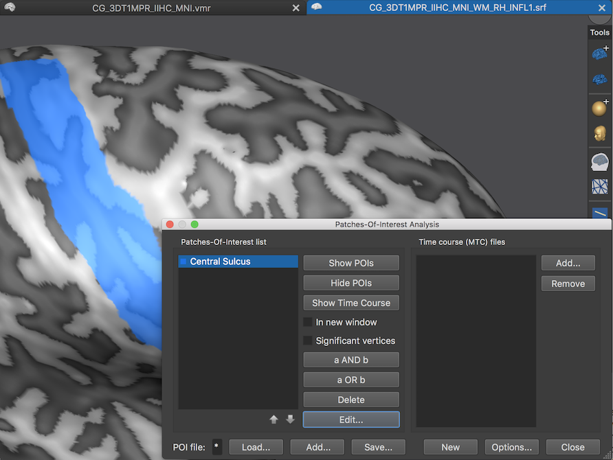
Since no POI was defined (or laoded) earlier for this mesh at this stage, the screenshot above shows only the newly defined POI in the Patches-Of-Interest list with the "Central Sulcus" name that has been entered in the Defne Patch-Of-Interest (POI) dialog for the example case. The name of a POI can also be added anytime using the Edit button after selecting the respective POI in the Patches-Of-Interest list. As with any POIs data, the defined POIs can also be saved to disk using the Save button or (re-)loaded (or added) using the Load and Add buttons, respectively. Note that only POIs can be loaded that match to the current mesh with respect to the number of mesh vertices. The New button can be used to remove all POIs. To define another POI, the Draw / Cut Mesh Mode icon need to be clicked again to re-enter POI drawing mode. When now another region is defined with the CTRL and CTRL+SHIFT keys and the left mous button, another color will be used corresponding to drawing color 2.
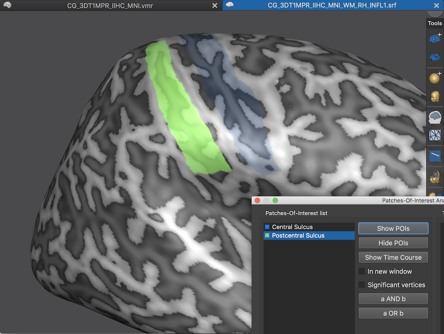
In the screenshot above a second region has been drawn and converted to a POI (see green color). Note that the first (blue) POI is slightly visible although only the second POI has been selected to be visualized using the Show POIs button in the Patches-Of-Interest Analysis dialog. The transparency of hidden POIs, as well as the transparency of selected POIs can be adjusted in the POI Analysis Options dialog.
Additional Features
There are several features available to modify and fine-tune the drawing process. In case that the currently drawn region is not accepted by clicking the Cancel button in the Define Patch-Of-Interest (POI) dialog, the current drawing is not removed allowing to continue drawing with the same drawing color after clicking again the Draw / Cut Mesh Mode icon to re-enteri POI drawing mode. More control over the drawing color can be obtained by clicking the Draw / Cut Mesh Mode icon while holding down the SHIFT key. This will launch the Mesh Drawing and Deletion dialog (see screenshot below). This dialog can also be launched by clicking the Painting and Cutting item in the Meshes menu.
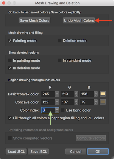
The dialog allows to select a drawing color using the Color index value box e.g. by using the up and down spin buttons (see green arrow above). Note that the drawing index is automatically incremented after accepting a POI - since we had defined two POIs above, it now shows drawing index 3, which, if not changed, would be used when drawing the next time on the mesh. The availability of separate color indices allows handling multiple drawings independently from each other avoiding that they are mixed when defining POIs.
When an error happens while drawing, e.g. when filling the whole mesh accidentally or drawing not at the desired location, one can go back to the last saved state by clicking the Undo Mesh Colors button (see red arrow above). This is possible since when starting drawing a contour while holding down the CTRL key or when filling an area against a contour by clicking with the CTRL and SHIFT key hold down, the colors before these actions are stored automatically when in drawing mode. One can also explicitly save the current colors of a mesh as an undo point using the Save Mesh Colors button, which may be useful when not in drawing mode. Note that only one undo point is stored, i.e. it is currently not possible to undo several drawing steps. It might thus be useful to draw extended contours
The color of each drawing index can be changed using the Back/convex color using the RGB value boxes or the Color selection button. Note that also a Concave color can be changed, which will be used eventually for regions of a mesh with concave curvature after running curvature calculation.
Copyright © 2023 Rainer Goebel. All rights reserved.