BrainVoyager v23.0
Manual ACPC and Talairach Transformation
In case that the automatic Talairach transformation of VMR data sets does not work satisfactorily, BrainVoyager allows to perform a manual ACPC and Talairach transformation. Talairach transformation is performed in two steps. In the first step, the cerebrum is translated and rotated into the AC-PC plane (AC = anterior commissure, PC = posterior commissure). In the second step, the borders of the cerebrum are identified; in addition with the AC and PC points, the size of the brain is fitted into standard space. These steps are perfomed in the Talairach tab of the 3D Volume Tools dialog (see below).
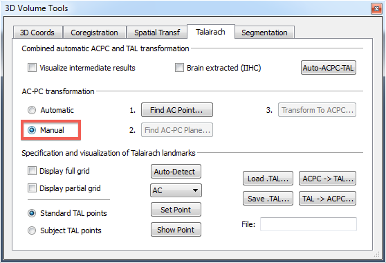
To start the interactive procedure, the Manual option needs to be selected in the AC-PC transformation field (see above). The buttons on the right indicate the three sub-steps of AC-PC transformation, including specification of the AC point (Find AC Point button), rotation in the mid-sagittal AC-PC plane (Find AC-PC Plane button) and actual transformation of the VMR data set into AC-PC space (Transform To ACPC button).
Specification of AC and PC
After clicking the Find AC Point button, the 3D Volume Tools dialog will be temporarily replaced by the Find AC Point dialog (see snapshot below). To find the anterior commissure, the cross can be positioned in one of the 3 sections of the orthographic 3D view showing the VMR data set in sagittal, coronal and axial orientation. For fine-grained adjustements, the spin controls of the Find AC Point dialog can be used or the cursor keys of the keyboard.
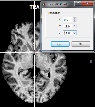
The snapshot above shows that the cross is positioned on the AC point in the axial view. It is helpful to cross-check the specified point by inspecting the cross position also in the other views. It may also be helpful to temporarily hide the cross using the "A" key. The AC point is accepted by clicking the OK button in the Find AC Point dialog. The dialog will disappear and the 3D Volume Toolsdialog will reappear. Furthermore, the 3D data set will be shown in a two-rows layout that is helpful for the next sub-step.
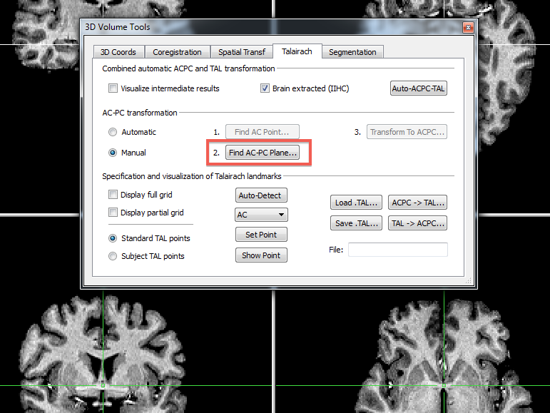
After clicking the AC-PC Plane button, the 3D Volume Tools dialog will be temporarily replaced by the Find AC-PC Plane dialog (see snapshot below) that is used to specify 3 rotation angles.
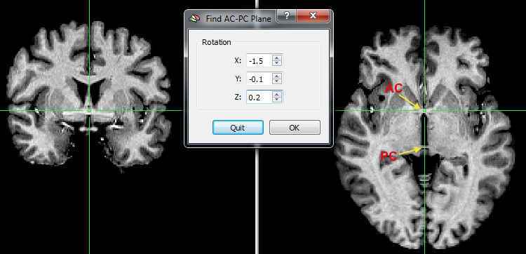
The rotation angles need to be adjusted in such a way that the PC point is visible on the axial slice and that the brain is placed in sagittal orientation. The X spin control in the Rotation field of the Find AC-PC Plane dialog is used to rotate the VMR dataset in the lower row until the view shows the posterior commissure in the axial plane (see snapshot above) and the horizontal line connects AC and PC in the sagittal plane. The Y spin box control is used to rotate the brain until the vertical green line runs through the middle of the brain in the coronal view. The Z spin box control is used to rotate the brain until the vertical green line runs through the middle of the brain in the axial view. These settings are accepted by clicking the OK button in the Find AC-PC Plane dialog. The dialog will disappear and the 3D Volume Tools dialog will reappear. Note that you can inspect and fine-adjust the defined translation and rotation parameters in the Coregistrationtab of the 3D Volume Tools dialog. The values in the Translation field reflect the displacement values that are necessary to move the original center of the 3D data set to the AC point, which will become the new center of the transformed data set. The rotation values in the Rotation field reflect the values that rotate the data set around the AC point such that the transformed data set will be "straight", i.e. in mid-sagittal orientation and that axial planes are coplanar to the the AC-PC plane.
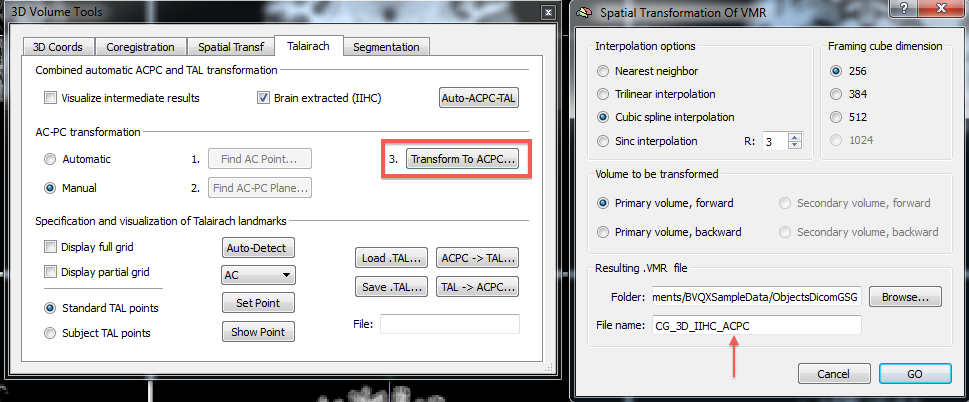
The specified AC-PC transformation is finally applied to the original data set by clicking the Transform To ACPC button (see above) creating a new data set as output in AC-PC space. The settings in the appearing Spatial Transformation Of VMR dialog (see above, right side) can all be accepted. Note that the resulting VMR file will receive the trailing substring "_ACPC" that will identify its name as being in AC-PC space. To perform the actual transformation, the GO button needs to be clicked. Note that this will also save a spatial transformation (TRF) file with the same name as the resulting VMR file (but with the ".trf" extension). The TRF file stores the rigid body transformation used to transform the original VMR data set into AC-PC space; it can be used subsequently to redo the transformation if desired, e.g. with a different interpolation method. The resulting VMR file is stored to disk and, for convenience, also loaded automatically in BrainVoyager's workspace so that the second step of Talairach transformation can be performed.
Specification of Cerebrum Borders
In the second step of Talairach transformation, eight reference points have to be specified within the AC-PC tranformed data set: AC, PC, AP (the most anterior point of the cerebrum), PP (the most posterior point), SP (the superior point), IP (the inferior point), RP (the most right point) and LP (the most left point). The AC point need (and should) not be changed because it is assumed to be the center of the ACPC data set.
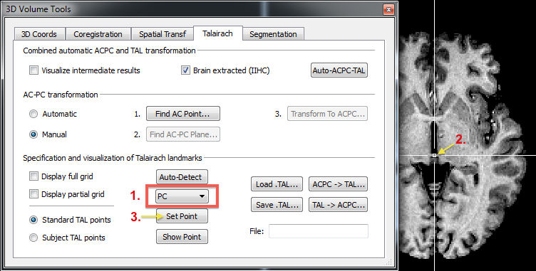
To specify the PC point, it needs to be 1) selected first in the Talairach reference points drop box (see snapshot above). Then 2) the cross needs to be positioned at the posterior commissure (see above) and 3) the Set Point button needs to be clicked in order to store the specified coordinate values. The same procedure needs to be performed for the remaining 6 reference points. Note that the cross is already located close to the target point based on knowledge of the actual Talairach space. Thus only fine-tuning adjustments need to be performed within the relevant direction. For the PC point, the cross needs to be moved in the posterior direction that can be performed best by using the Shift-Cursor-Down key combination.
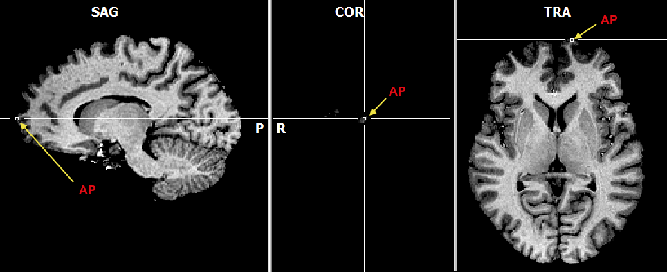
To specify the AP reference point, the white cross should be moved in the anterior-posterior direction (using Shift-Cursor-Up/Down) until the most anterior coronal slice is found that still contains (a bit of) grey matter (see snapshot above). Proceed analogously for the posterior point (PP).
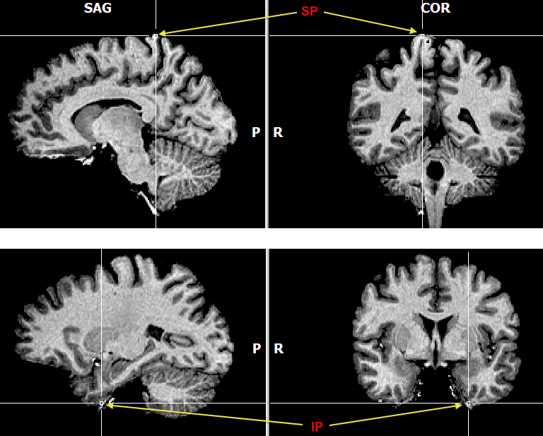
The superior and inferior points are defined in a similar way (see snapshots above). After selecting the respective point, the cursor up/down keys can be used to find the axial place with the last grey matter tissue in the superior (SP) and inferior (IP) direction. The left and right reference points are specified in a similar way. Note that the left point is on the right side and the right point is on the left side in case of the (default) radiological convention.
When all 8 landmarks have been defined, the specifications should be saved to disk by clicking the Save .TAL button in the Specification and visualization of Talairach landmarks field. The program suggests to use the same name as for the AC-PC VMR data set but with the extension ".tal". Saving the work is important since the stored .TAL information (together with the ACPC.trf file) is used later to transform functional data of the subject into Talairach space. To finally apply the Talairach "warping" step to the AC-PC data set, the ACPC -> TAL button needs to be clicked. As the resulting output file name, the program suggests a name that is the same name as used for the AC-PC VMR data set but the trailing "_ACPC" substring will be replaced with a "_TAL" substring. Note that the default transformation settings in the appearing Spatial Transformation Of VMR dialog use the Trilinear interpolation option for the transformation. You may consider switching to the Sinc interpolation option that runs much slower but produces better results (no implicit smoothing). As an alternative you may use fast (trilinear) interpolation but use the "reapply transformation" feature to run both steps (ACPC and TAL) in a single transformation with the sinc interpolation option. After accepting the transformation settings, the program will save and, for convenience, load the resulting TAL VMR file after the transformation step is complete.
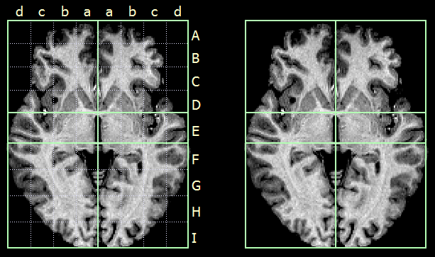
Since the brain is now in Talairach space, the Talirach standard boundaries can now be visualized and should pefectly match to the transformed subject brain. You may check the Display partial grid option or the Display full grid option in the Talairach proportional grid reference points field. These reduced (see right side above) and full grid visualizations (see left side above) match the defined proporitonal grid system as defined by Talairach and Tournaux (1988). Note also that the position of the cross will now be presented as Talairach coordinates (besides the standard BrainVoyager coodinates) in the 3D Coords tab of the 3D Volume Tools dialog.
Copyright © 2023 Rainer Goebel. All rights reserved.