BrainVoyager QX v2.8
Multiple Anatomical Data Sets
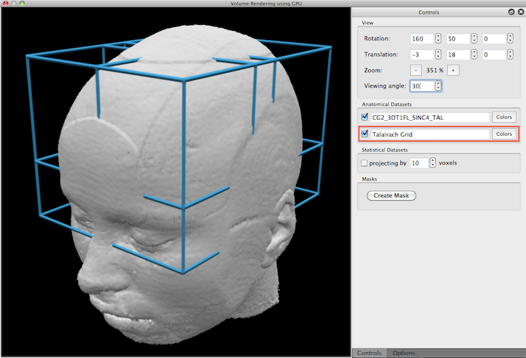
When the volume renderer is launched, the current VMR serves as the main volume for rendering. If the current VMR has been transformed in Talairach space, a second volume is automatically added that contains the standard Talairach grid (see snapshot below). Since only the main volume is turned on for rendering initially, the "Talairach Grid" volume needs to be checked in order to include it in volume rendering (see red rectangle below). If the current VMR (and any other added VMR, see below) is in radiiological convention (see VMR Properties dialog), the left/right axis will be flipped prior to rendering so that the volume renderer always produces a correct 3D rendering.
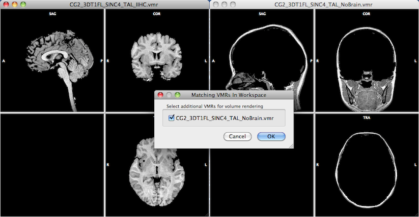
In order to include further volumes for rendering, additional VMRs need to be opened in the workspace before starting the volume renderer. In the snapshot below, two volumes were loaded before launching volume rendering with the one on the left side ("CG2_3DT1FL_SINC4_TAL_IIHC.vmr") as the active document. After clicking the Real-Time Volume Rendering menu item, BrainVoyager checks wether the workspace contains other VMR documents that fit to the active VMR. If there are other VMRs that have the same dimensions as the active VMR, they are offered for inclusion in volume rendering and listed in the appearing Matching VMRs in Workspace dialog. In the example below, the only matching VMR is the document on the right side ("CG2_3DT1FL_SINC4_TAL_NoBrain.vmr"). All matching VMRs are selected for inclusion as default; one can use the check marks to unchecked documents that should not be included.
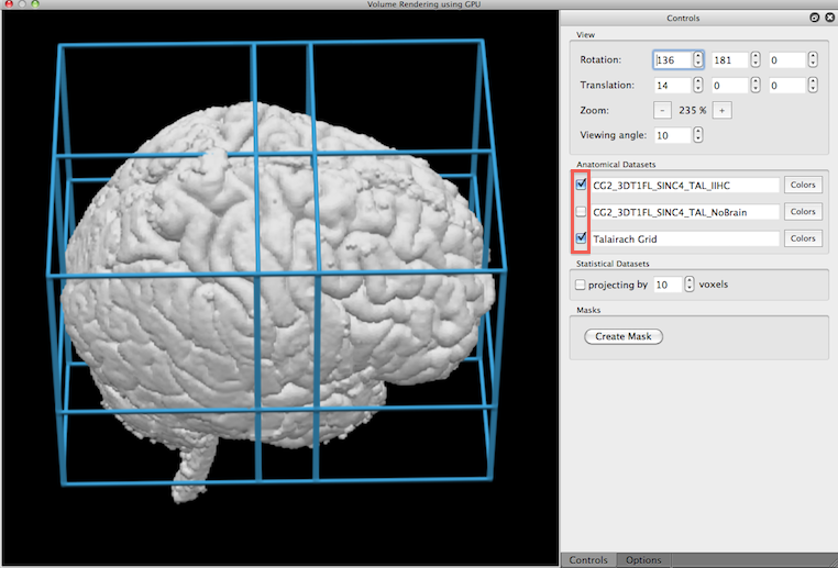
The active VMR and all additionally included VMRs will be listed in the Anatomical Datasets field of the Volume Rendering Window. The check boxes on the left side of each name can be used to include/exclude a specific volume for rendering. In the snapshot below, the active VMR as well as the added Talairach grid VMR has been selected.
When multiple VMR documents are included, it is often helpful to assign a different color to each data set. Colors may be assined by clicking the Colors button on the right side of the Volume name text box of a volume (see rectangle 1 in snapshot below). The appearing Color Table dialog allows to assign colors for specified intensity ranges; as default, one color range (50 - 255) is defined which is assigned to the color white (RGB = [255, 255, 255]). To change the color assignment, click the Color button (see rectangle 2) that will invoke a (platform-specific) color specification dialog. In the snapshot below the color of the brain volume has been changed to light yellow.
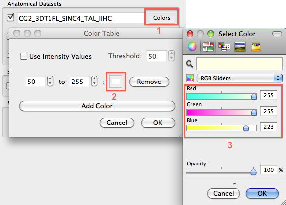
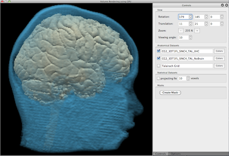
The color specification dialog not only allows to set the red, green and blue component of a color but also allows to change transparancy (see Opacity slider in the snapshot above). In the rendered view below, the second volume ("NoBrain") has been assigned a blue color with a low opacity (hight transparency) value (10%) that allows to see the primary brain volume through the head tissue.
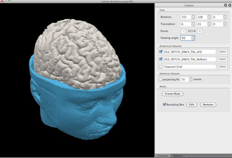
Besides transparancy, multiple volumes can also be visualized by using cuts (for details see topic Masking and Cutting). The snapshot below shows an example in which the "NoBrain" volume has been cut to allow a view on the top part of the brain volume.
Besides purely anatomical images, the real-time volume renderer allows to integrate volume maps that can be visualized in various way together with anatomical data.
Copyright © 2014 Rainer Goebel. All rights reserved.