BrainVoyager QX v2.8
IA Using Header-Based Coregistration
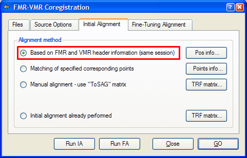
Header-based mathematical coordinate coregistration is the preferred strategy for the initial alignment step yielding excellent results. It requires only that the used 3D data set is recorded in the same session as the functional data set and that the file format used to import the data into BrainVoyager QX contains the required positioning information in the header of the functional and 3D anatomical. This is the case for DICOM data, Philips REC/PAR data and GE_I data, but not, for example, for the Analyze file format. To use this initial alignment strategy, make sure that the Based on FMR and VMR header information (same session) option is turned on in the Initial Alignment tab of the FMR-VMR Coregistration dialog (see snapshot below). Since this is the preferred alignment strategy, this option is turned on as default.
To start the mathematical header-based initial alignment procedure, either click the Run IA button or the GO button. In the latter case, the fine-tuning step is automatically started after the initial alignment step. To see the initial alignment result in isolation, use the Run IA button. After a short moment, the result of the header-based alignment is shown in the VMR View window. A snapshot of the alignment result for the "Objects" example data set is shown below.
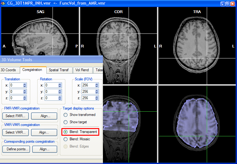
To judge by eye the quality of the alignment, the program shows two rows with three views, the upper showing the target VMR data and the lower showing the functional data in various combinations with the target VMR. As default, the functional and anatomical data are shown in transparency blend mode, which can be turned on by checking the Blend: Transparent option in the Target display options field of the Coregistration tab of the 3D Volume Tools. In transparencey blend mode, the transformed (scaled, rotated, translated) functional data set (one volume) is shown as default with a transparency value of 0.5. You may change the transparency blending value by clicking CMD-Cursor-Up and CMD-Cursor-Down on Mac OS X or CTRL-Cursor-Up and CTRL-Cursor-Down on Windows and Linux. Cycling through different transparency values by repeatedly pressing these buttons aids in judging the achieved alignment. Besides using the cursor up/down keys, you may also change the transparency blending value in the Blend mode transparency field in the Coregistration Options dialog, which can be invoked by clicking the Options button in the FMR-VMR Coregistration tab.
Note that you can move the cursor in the VMR data set to any desired region, which also helps to judge the alignment result. You can check the result also by looking at the cross position in the upper row and the cross position in the lower row, which should show the same brain region after successful alignment. You may also toggle between the anatomical and functional data set in the lower row by selecting the Show transformed or Show target option.
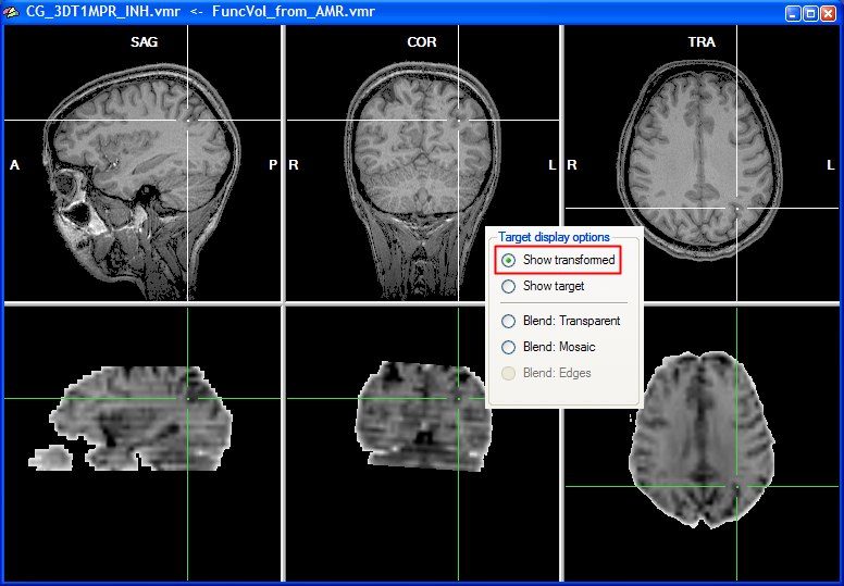
As a convenience function, you can click repeatedly on the Show transformed option (or Show target option) to toggle between the functional and anatomical volume in the lower row. This allows to check the alignment without having to look back at the 3D Volume Tools dialog. As an additional mode, you can turn on mosaic blend mode by checking the Blend: Mosaic option. In this mode, either the anatomical or the functional data is shown in neighboring square regions ("checks") forming a checkerboard display. You may change the size of the checks in the Check size field in the Coregistration Options dialog, which can be invoked by clicking the Options button in the FMR-VMR Coregistration tab.
Note that the mathematical header-based alignment would be perfect if no motion would occur between the anatomical and functional recording and the two data sets were recorded without any geometric distortions. In most recent scanners, geometric distortions are minimal not only for anatomical but also for functional (EPI) scans. Small head motions between the two scans might, however, occur which can be corrected using the fine-tuning alignment step.
Background information
The header-based alignment procedure starts by checking whether header information about slice positioning is available for the two data sets (FMR, VMR). BrainVoyager QX saves the respective slice positioning information from the original images directly into newly created FMR and VMR files. If header information is not available, it shows the FMR-VMR Same-Session Alignment Using Position Data dialog (for details, see below). The mathematical header-based alignment is able to coregister the two data sets for any slice orientation. In order to work properly, the FMR-VMR alignment must, however, respect what kind of transformations have been potentially applied to the data sets after project creation. The program assumes that no change to the FMR file has been made after project creation but changes to the VMR file prior to alignment are known to the program because they are saved into the transformed VMR file. If, for example, a VMR file, which has been originally recorded in axial slices, has been transformed into the standard sagittal orientation of BrainVoyager, the FMR-VMR alignment would fail if it would not know about this transformation because it would transform the functional data to match the original axial VMR orientation. To allow proper alignment respecting spatial transformations applied to the VMR file, those transformations are saved directly in the transformed VMR file together with the original positioning information. If an axial VMR (i.e. "S1_3D.vmr") is, for example, transformed into sagittal orientation, the saved sagittal VMR (i.e. "S1_3D_SAG.vmr") will contain this transformation information. When the header-based alignment procedure is started, QX checks both the information of the scanning position information as well as any spatial transformation recorded in the VMR header in order to compute the correct mathematical spatial transformation.
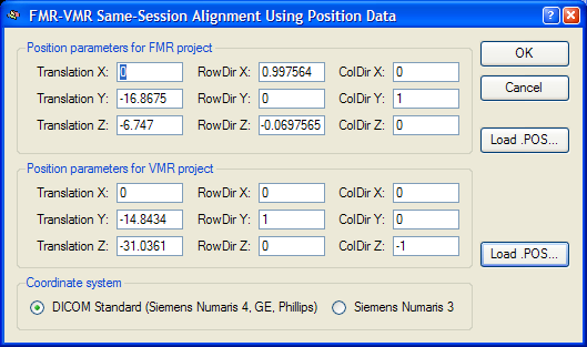
External position information. BrainVoyager QX not only saves positioning information directly in the FMR and VMR files, but also saves that information in separate external files with the extension ".POS". These files were necessary in BrainVoyager 2000 but are normally not used in BrainVoyager QX. In case that the mathematical header-based alignment has been chosen, but the original data does not contain positioning information, the FMR-VMR Same-Session Alignment Using Position Data dialog will appear when clicking Run IA (or GO) asking for entering manually the positioning information. If custom-created position information (or correct position information from other BrainVoyager files) is available, these POS files can be loaded using the Load .POS buttons for the FMR and VMR file, respectively. If FMR and VMR projects are created with BrainVoyager QX from raw data with the respective positioning information, you will not see this dialog during coregistration. To inspect the positioning information used for mathematical header-based alignment, you can, however, click the Pos info button in the Alignment method field of the Initial Alignment tab, which will invoke the position information dialog (see snapshot below). The fields define transformation parameters for a virtual slice running exactly through the center of the slab (image volume) covered by the functional (FMR) and 3D anatomical (VMR) scan, respectively. The first column (Translation X, Translation Y and Translation Z values) of the parameters define the translation of the centre point of the virtual centre slice with respect to the iso centre of the magnet. The second and third columns (RowDir X, RowDir Y, RowDir Z and ColDir X, ColDir Y and ColDir Z parameters) define direction vectors specifying the orientation of the scanned slices of the functional and anatomical scans within the scanner reference system using two direction vectors. For the header-based alignment, the relative orientation difference in orientation of the FMR data with respect to the VMR data can be computed and is used for the alignment (for details on the mathematical background, consult the "Spatial transformations in BrainVoyager QX" documentation).
Copyright © 2014 Rainer Goebel. All rights reserved.