BrainVoyager QX v2.8
Simultaneous EEG-fMRI: FMRI Artifact Detection and Removal
Introduction
The simultanoues acquisition of fMRI and EEG offers a potential added value to the simple combination of the two modalities, represented by the possibility of studying the EEG-fMRI coupling effects. Unfortunately, raw EEG data collected during fMRI experiments are contaminated by characteristic artifacts of both technical and physiological origins, such as the gradient (GRA) artifacts, related to the switching of magnetic field gradients, and the ballistocardiographic (BCG) artifacts, related to cardiac activities.
The FMRI Gradient (GRA) artifact
During MR imaging, the magnetic field inside the MRI scanner continuously changes due to the switching of the gradients. In echo planar imaging (EPI), gradient switching is repeated each time a new slice is acquired, resulting in repeated artifacts on simultaneously acquired EEG channels. The amplitude of these MR gradient artifacts (GRA) is typically 100 times greater than the normal EEG signal amplitude while their frequency content overlaps with that of the EEG, preventing them from being simply filtered out by standard filtering.
The most used method to remove gradient artifacts from EEG signals collected during fMRI is the average artifact subtraction (AAS), which was first introduced by Allen et al. (2000) and utilizes the repetitiveness of the artifact shape to form an average artifact template, which is then subtracted from the raw EEG data. Even if the GRA artifacts can be sometimes removed "on-line" via the EEG device software, BrainVoyager QX offers a AAS-based plugin called EMEGFMRIArtifactPlugin that not only auto-detects and aligns all slice GRA artifacts, thereby defining precise triggers, but also removes them from EEG traces using the AAS technique.
The Ballisto-cardiogram (BCG) artifact
The BCG artifact is due to pulsatile scalp and blood movement under the electrodes and is therefore temporally related to cardiac cycles. Inside the magnet, the magnitude of the BCG artifact signal can be more than 3-4 times that of the EEG, spreading throughout the heart beat period; despite its repetitiveness, the BCG artifact is much less stable than the GRA artifact and both the magnitude, the time scale and the shape can vary substantially from beat to beat and from channel to channel. For this reason, using the AAS method, in combination with, e. g., a QRS detector operating on the ECG channel (if available) to detect the heart beats, often results in excessive residual artifacts in the EEG data and more sophisticated approaches and procedures are required to better evaluate the temporal and spatial lay-out of the BCG artifact.
One frequently used approach consists in the channel-wise collection of all BCG artifact exemplars for the definition of an Optimal Basis Set (OBS) of signals to be used for capturing not only the average shape like in AAS but all relevant temporal variations of the BCG artifact, to be included in a (typically linear) detrending stage.
In alternative (or, better, in addition) to OBS, when multiple EEG channels are recorded, blind source separation (BSS) techniques can be fruitfully used to recover artifact sources from all recorded channels in the form of multi-channel components, thereby taking into account as much as possible of the "spatial structure" (i. e. the topological regularity) of the BCG artifact, that is neglected by OBS. These BCG artifact related components can be subsequently removed from the EEG data (after component selection) via channel time-course (typically linear) recontruction. The most widely reported BSS technique for BCG artifact removal, is Independent Component Analysis (ICA), that models each channel time-course as a linear mixture of statistically independent source signals and typically allows extracting one or more BCG artifact related components; thereby, ICA can be used to clean up the EEG traces in the linear reconstruction stage after identification and selection of these components.
NOTE: While being insensitive to temporal variations and instabilities of the underlying BCG artifact source, the ICA model strongly relies on the assumption of "spatial stationarity" of the source processes. Since this assumption is not strictly valid for the BCG artifact (at least for the entire data segment), ICA can split the BCG source into multiple components and extract more than one BCG components, thereby rendering the subsequent stage of BCG artifact component identification and selection more difficult. Some authors (see, e. g., Debener et al., 2007) suggest to apply OBS prior to ICA (OBS+ICA approach) to combine the strengths of both methods by removing the major part of the artifact with OBS and its residuals with ICA.
Whether or not used in combination with ICA, another limitation of the AAS and OBS approaches is represented by the fact that all artifact examplars are subtracted within a fixed time interval. This is an important limitation for BCG artifact removal because the actual duration of each single pulse is strongly variable across the entire data segment. In order to correct for different durations, a non-linear approach is needed. For instance, once all pulses have been detected, a non-linear time warping (NLTW) procedure can be applied that iterative warps all pulses along the time axis to the same duration while maximizing their total cross-correlation. If this procedure is reversible, it is possible to apply AAS or OBS to the time-warped versions of the pulses and, then, replace the data segments with the suppressed pulses in the original time-series after restoring the original time scale.
Application
Starting from BrainVoyager QX 2.4, it is possible to detect and remove GRA and BCG artifacts from EEG continous time-course (CTC) data sets by running a computational plugin called EMEGFMRIArtifactPlugin available from the Plugins menu. This plugin uses highly optimized routines for the AAS and OBS methods and only requires to provide the CCD file that contains all relevant information about the current data set, including the (linked) channel time-course (CTC) file. Schematically, the plugin performs the following tasks:
1) Robust automatic EEG-based detection of fMRI sequence parameters.
2) Optimised AAS-based GRA correction with high-resolution templates (obtained via cubic spline interpolation).
3) Robust automatic EEG-based detection of heart pulse triggers (using informaiton from all channels).
4) Optimised OBS-based BCG artifact correction with non-linear time modeling of the heart pulses.
All detected GRA and BCG artifact triggers (in steps 1 and 3) are written to a BrainVoyager QX protocol file which can be used to visualize and quantify the occurrence and the impact of the fMRI artifacts on channel or component time-course data in the Preprocessing tab of the EMEG Suite.
NOTE: When running the EMEGFMRIArtifactPlugin it is always possible to skip any of the two stages of GRA detection/correction and BCG detection; however, it is strongly recommended to always remove all GRA artifacts from the data before proceeding with the detection and correction of BCG artifacts.
Illustration of the FMRI Gradient artifact correction procedure
In order to minimize the residuals of the GRA correction procedure, a high EEG sampling frequency is needed (1-2kHz or more) for the input data set. Therefore, it is highly recommended not to decimate (nor filter) the EEG time-series when importing raw data to BrainVoyager before running the EMEGFMRIArtifactPlugin. The GRA correction procedure operates chanel-wise. A diagram of the whole process is shown below.
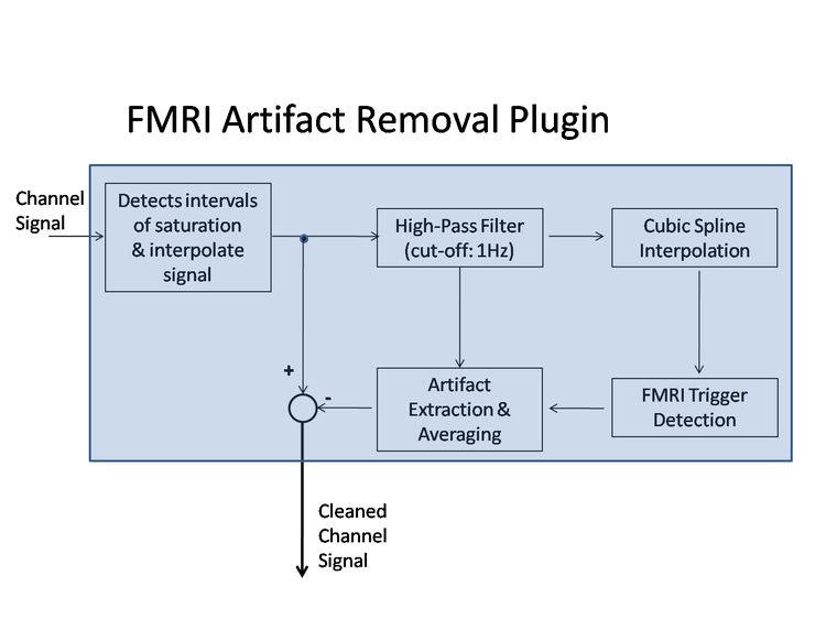
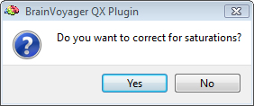
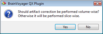
Before entering the core GRA artifact detection and correction process, possible intervals of signal saturation caused by extremely high artifact values can be automatically detected from the data and corrected via interpolation. Ideally these amplitude saturations should be avoided as much as possible by adjusting appropriately the EEG acquisition parameters, since EEG data is irreversibly lost whenever saturation occurs. Then, MRI parameters such as number of volumes, number of slices, volume duration, slice duration and inter-volume time gap are automatically detected. The user can decide whether correcting for saturations and performing the GRA artifact correction slice-wise (recommended) or volume-wise:
From the signal processing viewpoint, it is important to keep in mind that during simultaneous EEG-fMRI acquisition, the first EEG time sample of each MRI slice does not always occur at the same time after the MRI slice trigger. The reason is that the fMRI inter-slice and inter-volume time intervals are most of the time non-integer multiples of the EEG sampling rate. Some specific EEG-fMRI hardware (SYNCHBOX) can partly solve this issue by synchronizing the beginning of each MRI volume acquisition to the beginning of an EEG sample, although individual MRI slices within the same MRI volume are usually left unsynchronized. As a consequence of this desynchronization, the sampling sequence of each MRI slice is progressively shifted over time with respect to the MRI slice trigger. Since the spectral content of the MRI gradient artifact extends towards high frequencies which are close to the EEG sampling rate, this progressive sampling shift prevents from reconstructing each slice in an identical way, and thus from properly gathering information from different slices in order to build an artifact template. To solve this issue the EEG signal is upsampled to provide sufficient time resolution and accurately reconstruct the MR gradient artifacts from the EEG data. In this plugin a cubic spline representation (see, e. g., Koskinen et al., 2009) is applied to a 1Hz high-pass filtered version of the data, which allows to build a high-quality MR gradient artifact template. In addition, the artifact template is also adjusted depending on local temporal variations of the MR gradient artifact between subsequent artifacts templates. This is done by using interpolating polynomials that ensure a smooth 2nd-order amplitude continuity and contribute to providing an overall very high quality MR gradient artifact correction. The user can check (and modify is necessary) the default window half-length in slices:

Below you can see an example of results obtained with this plugin, with an EEG signal before and after application. In this example, EEG and fMRI were simultanouesly acquired with an "interleaved" scheme which allows to compare the raw EEG traces during intervals with and without the GRA artifact. The high quality of the results is confirmed by the fact that the two signals almost perfectly overlap in the absence of an artifacts, whereas the pattern structure is substantially preserved between consecutive intervals with and without artifacts.
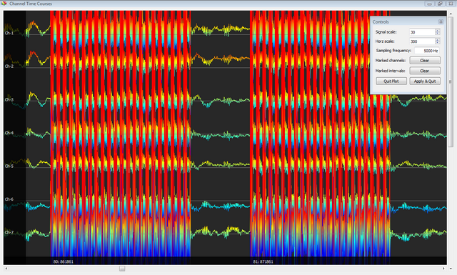
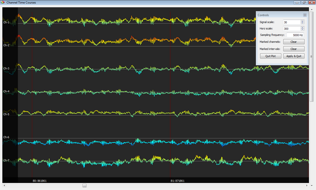
Illustration of the BCG artifact correction procedures
In order to detect all BCG artifacts, a four-step procedure is followed. First, an initial search of the heart pulses is performed, using an iterative look-up procedure ensuring maximization of the total pulses' cross-correlation as well as minimization of their variability within a range of preselected selected time offsets. This procedure fully exploits multi-channel information and full sampling rate to optimize detection quality. Second, for each channel, an optimal pulse signal is built using the 50% most representative normalized pulses (obtained from previous step) and, third, this representative pulse is useto build up a heart pulse indicator (HPI) function, i. e. a function that has all well-contrasted peaks indicating each heart pulse. Forth, a multi-channel peak analysis is performed using HPIs from all channels, which yields the final heart pulse triggers that are saved to a PRT file.
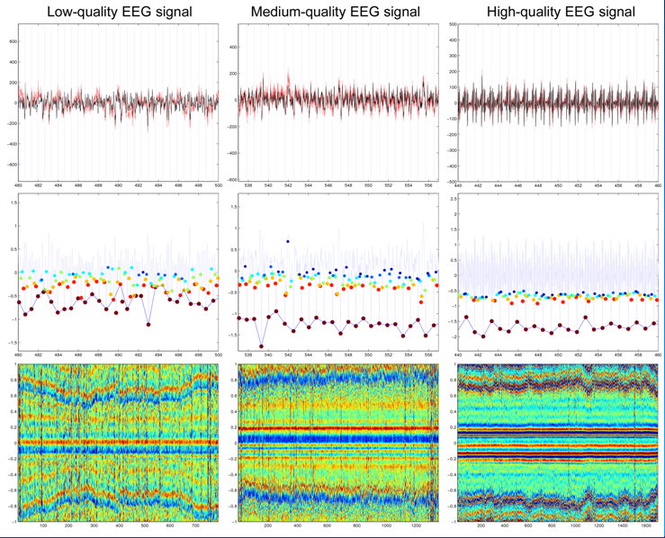
In the next figure, three examples of EEG data sets of different qualities (low, medium and high) are shown in the first row. All traces are GRA-free but are highly corrupted by BCG pulses. The corresponding HPI functions (middle row) and the single trial images resulting from the detected pulses (last row) are also shown after the BCG detection procedure. In the HPI series the peaks corresponding to "selected" pulses are marked in darked red, whereas the discarded candidate peaks/pulses are marked in other colors (in order of ranking: red, yellow, blue and cian). Even if the HPI is much more contrasted in the high-quality EEG signal, in all three cases the resulting single-trial images clearly show the structure (and the variability) of the detected artifacts with a relatively low number of missed artifacts. Particularly, the high variability of the duration of the pulses is evident.
The BCG artifact correction is also performed in four steps but now independently for each channel on 250Hz decimated data. First, an optimal non-linear time warping (NLTW) of each pulse signal is computed using an iterative procedure that constrains all heart pulses to have the same duration while maximizing their total cross-correlation. Second, based on the estimated NLTW transforms, equal-duration and partly-overlapping pulses are generated for the entire time-series and, third, an OBS is perfomed on the time-equalized pulses, using just the first three principal components. Forth, the obtained channel-specific heart pulse artifact model is transformed back to the original time scale, upsampled to the original data resolution using cubic spline interpolation, and finally substracted from the original data. The overlaps introduced in step 2 ensure continuity of the pulse correction.
Here is an example of the detected and aligned pulses in the original time scale (left) and the non-linear time-warped scale. Especially, towards the end of the pulse (bottom part) the alignment is much better for the NLTW pulses, allowing to anticipate that the subtraction in this transformed time axis will be more effective.
NOTE (1): Time-domain averaging of the both BCG-uncorrected and BCG-corrected epochs can be easily obtained by simply loading the resulting CTC files to the EMEG Preprocessing tab of the EMEG suite together with the protocol with all BCG artifact triggers. Before running the single-trial extraction, it is necedssary to adjust pre- and post-trigger intervals to 500ms and 1200ms as well as increase the artifact thresholds to ensure a correct definition of pulse duration and avoid discarding some of the artifacts because of the amplitude of the peaks (normally 3-4 times higher than standard EEG signals). This allows to easily compare the outcome of the procedure.
NOTE (2): Even if the EMEGFMRIArtifactPlugin can detect and remove completely all BCG artifacts, it is always possible to use a more classical procedure where the generate BCG artifact triggers are combined with an BCG-uncorrected version of the data in a separate OBS stage, eventually followed by an ICA.
IMPORTANT: When processing EEG data in separate OBS and/or ICA stages, it is always recommended to reduce the sampling rate from the typical values required for GRA correction (>1kHz) down to values <<1kHz, e. g. 250 or 200 Hz. In fact, this sampling rate fully preserves the BCG artifact source information in the data, while keeping OBS and ICA calculations feasible in all practical situations. As mentioned above, in the EMEGFMRIArtifactPlugin, this decimation is done internally but the data are upsampled back to their sampling rate. If necessary, a time decimation by a suitable factor (e.g. 20 to change the sampling rate from 5kHz to 250Hz) can be obtained via the EEG/MEG Filter dialog.
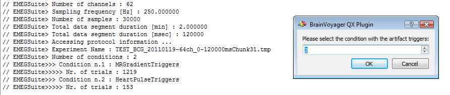
When running the EMEGArtifactRemovalPlugin for applying OBS, the CTC file with the GRA-corrected BCG-uncorrected time-decimated EEG data sets should be supplied. In addition to the CTC, the PRT file with BCG artifact triggers, as generated by the EMEGFMRIArtifactPlugin (with the BCG correction activated) should be supplied as well. The plugin will prompt the user to specify the the protocol condition related to the detected BCG artifacts:
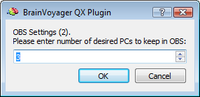
For OBS-based BCG correction, the EMEGArtifactRemovalPlugin plugin uses all heartbeat events as detected by the EMEGFMRIArtifactPlugin to generate and subtract a BCG template from the continuous data. To this purpose, the continuous data are epoched relative to the heartbeat events and groups of consecutive epochs, also called segments, are aligned in a matrix to calculate the corresponding principal components (PCs). Then, for each segment, a predefined number of PCs (normally 3 is a good choice) are taken to form the OBS and, finally, the OBS signals are least-squares-fitted and subtracted from each segment. Note that this procedure is performed separately for each channel.
Time-domain averaging of the BCG-corrected epochs can be easily obtained by simply loading the resulting OBS-corrected CTC to the EMEG Preprocessing tab of the EMEG suite together with the protocol with all artifact triggers, specifying the HeartBeatPulse as protocol condition for epoching and adjusting pre- and post-trigger intervals (as well as artifact thresholds) for a correct selection of all BCG intervals.
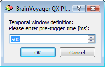
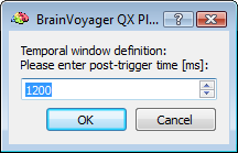
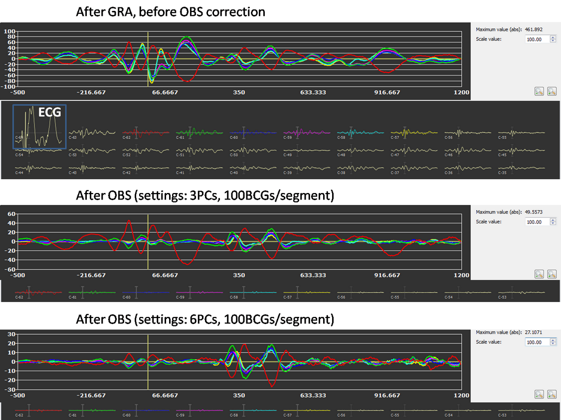
After preparing a back-up of the CTC data set, the EMEGArtifactRemovalPlugin prompts the user (i) to specify the pre- and post-trigger interval definition (default choices are 500ms and 1200ms that conservatively ensure the coverage of all hear beats), (ii) the number of artifacts (i. e. heat beats) to include in each segment before correction (default choice is 100) and (iii) the number of PCs to keep for OBS:
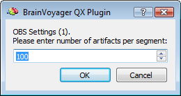
NOTE: The OBS settings can be sometimes adjusted to optimise the results. For instance, increasing the number of artifacts per segment allows for better modeling of the BCG artifact and its variability, however this also increases the computational load and reduces adaptivity; on the contrary reducing the number of artifacts per segment allows for faster calculations and higher adpativity to BCG shape and timing changes, however the number of examplars is lower and so worse will be the SNR of the OBS model of the BCG and higher will be the risk of capturing non-BCG related variability.
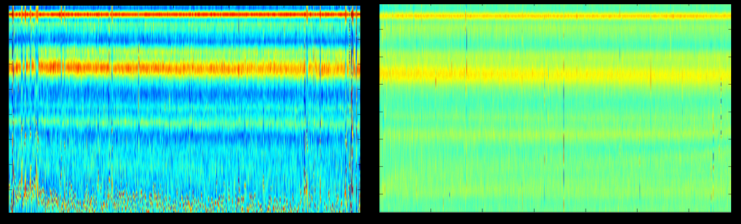
Even if default settings are already optimised (and therefore expected to cover many practical cases), it is sometimes useful to fine tune the OBS settings by comparing the BCG averaged data before and after PBS correction, as shown in the figure below, where it is possible to appreciate the substantial reduction of the BCG artifact magntitude by the performed OBS correction, especially around the BCG trigger.
A further alternative to deal with the BCG artifacts is given by the possiblity to run a temporal ICA on the data set via the EMEGTemporalICAPlugin. This can be done before or after a OBS stage. After running the EMEGTemporalICAPlugin plugin on the GRA/OBS-corrected (decimated) data sets it is possible to visualize the resulting component time-courses together with the protocol generated by the EMEGFMRIArtifactPlugin in the channel preprocessing tab of the EMEG Suite as for any CTC data set.
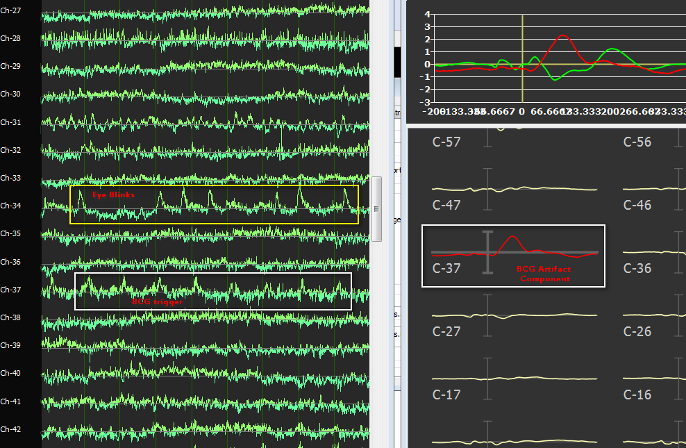
The protocol with artifact triggers can also be used to epoch and average the EEG (component) traces in the EMEG Suite. In fact, the same protocol with artifact triggers can be used to identify individual BCG artifacts as well as to epoch and average the EEG traces with respect to the BCG triggers, thereby visualizing the "original" and "residual" artifact before and after component selection and removal, as illustrated by the next figure below. Here, the BCG triggers contained in the protocol generated by the EMEGFMRIArtifactPlugin are overlaid to the ICA component time-courses and used to calculated an BCG-related "potential". Scrolling the ICA component activities allows to recognize components that are highly time-locked to BCG triggers (and therefore good candidates for removal) as well as components that are clearly not time-locked to BCG triggers (e.g. related to other types of artifacts such as eye blinks).
References
Allen, P.J., Josephs, O., Turner, R., 2000. A method for removing imaging artifact from continuous EEG recorded during functional MRI. Neuro- Image 12, 230- 239.
Debener, S., Strobel, A., Sorger, B., Peters, J., Kranczioch, C., Engel, A.K., Goebel, R., 2007. Improved quality of auditory event-related potentials recorded simultaneously with 3 T fMRI: removal of the ballistocardiogram artifact. NeuroImage 34, 587-597.
Koskinen,Koskinen, M., Vartiainen, N., 2009. Removal of imaging artifacts in EEG during simultaneous EEG/fMRI recording: Reconstruction of a high-precision artifact template. NeuroImage 46, 160-167.
Mantini, D., Perrucci, M.G., Cugini, S., Ferretti, A., Romani, G.L., Del Gratta, C., 2007. Complete artifact removal for EEG recorded during continuous fMRI using independent component analysis. NeuroImage 34, 598-607.
Niazy, R.Niazy, R.K., Beckmann, C.F., Iannetti, G.D., Brady, J.M., Smith, S.M., 2005. Removal of FMRI environment artifacts from EEG data using optimal basis sets. NeuroImage 28, 720-737.
Copyright © 2014 Fabrizio Esposito and Rainer Goebel. All rights reserved.